ENGINE
Inspecting the Cylinder Block and Components
12/05
6LY3 Service Manual
5-41
© 2007 Yanmar Marine International
Inspecting the Connecting Rods
The connecting rod (Figure 5-48, (1)) is made of
high-strength forged carbon steel. The large
crankshaft bearing is equipped with a bearing cap
and a 2-piece aluminum bearing insert assembly.
The piston pin bearing (Figure 5-48, (2)) is a
non-serviceable copper alloy bushing that is
factory-installed.
Figure 5-48
Figure 5-48
1 – Connecting Rod
2 – Piston Pin Bearing
3 – Crank Pin Bearing Inserts
4 – Connecting Rod Cap
5 – Connecting Rod Cap Bolts
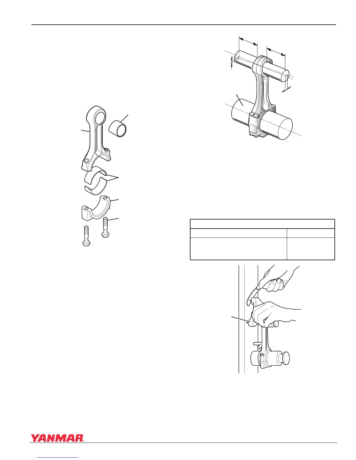
Inspecting the Connecting Rod Bearing
Alignment
Ensure that the connecting rod is not twisted.
• Insert the appropriate mandrel
(Figure 5-49, (3)) into both ends of the
connecting rod.
Figure 5-4 9
Figure 5-49
1 – Parallel Measurement
2 – Twist Measurement
3–Mandrel
• Measure alignment.
• Replace connecting rod if it exceeds the stated
limits.
Figure 5-5 0
Figure 5-50
1 – Connecting Rod Tool
2 – Twist Measurement Using a Rod Alignment
Tool
0005632
(2)
(3)
(5)
(4)
(1)
Connecting Rod Twist
Standard Limit
Less than 0.05 mm
(0.0019 in.)
(at 100 mm (3.936 in.))
0.07 mm
(0.0027 in.)
0005633
(1)
(2)
(3)
100mm
100mm
0005634
(1)
(2)

 Loading...


