TURBOCHARGER
Assembling the Turbocharger
9-20 6LY3 Service Manual
© 2007 Yanmar Marine International
3. Install the turbine-side outer retaining rings into
the bearing housing.
4. Position the compressor-side floating bearing in
the groove in the bearing housing.
Installing the Turbine Rotor Shaft
Keep all parts coated with clean engine oil when
assembling.
1. Position the seal ring on the turbine rotor shaft.
2. Position the turbine housing on the turbine rotor
side of the bearing housing.
Note: Set the retaining ring so its round side
faces the bearing.
3. Insert the turbine shaft into the bearing housing
from the turbine side. NOTICE: Avoid damaging
the floating bearing with the turbine rotor shaft.
4. Face the slot of the seal ring toward the oil inlet
and align the seal ring with the turbine rotor
shaft.
Installing the Thrust Bearing
1. Install the thrust bearing on the turbine rotor
shaft.
2. Apply engine oil to the thrust bearing and place
the thrust bearing in the bearing housing.
3. Use M3 TORX T machine bolts and tighten to
the specified torque value.
Installing the Seal Plate
1. Install the seal rings to the oil thrower.
2. Set the oil thrower in the seal plate.
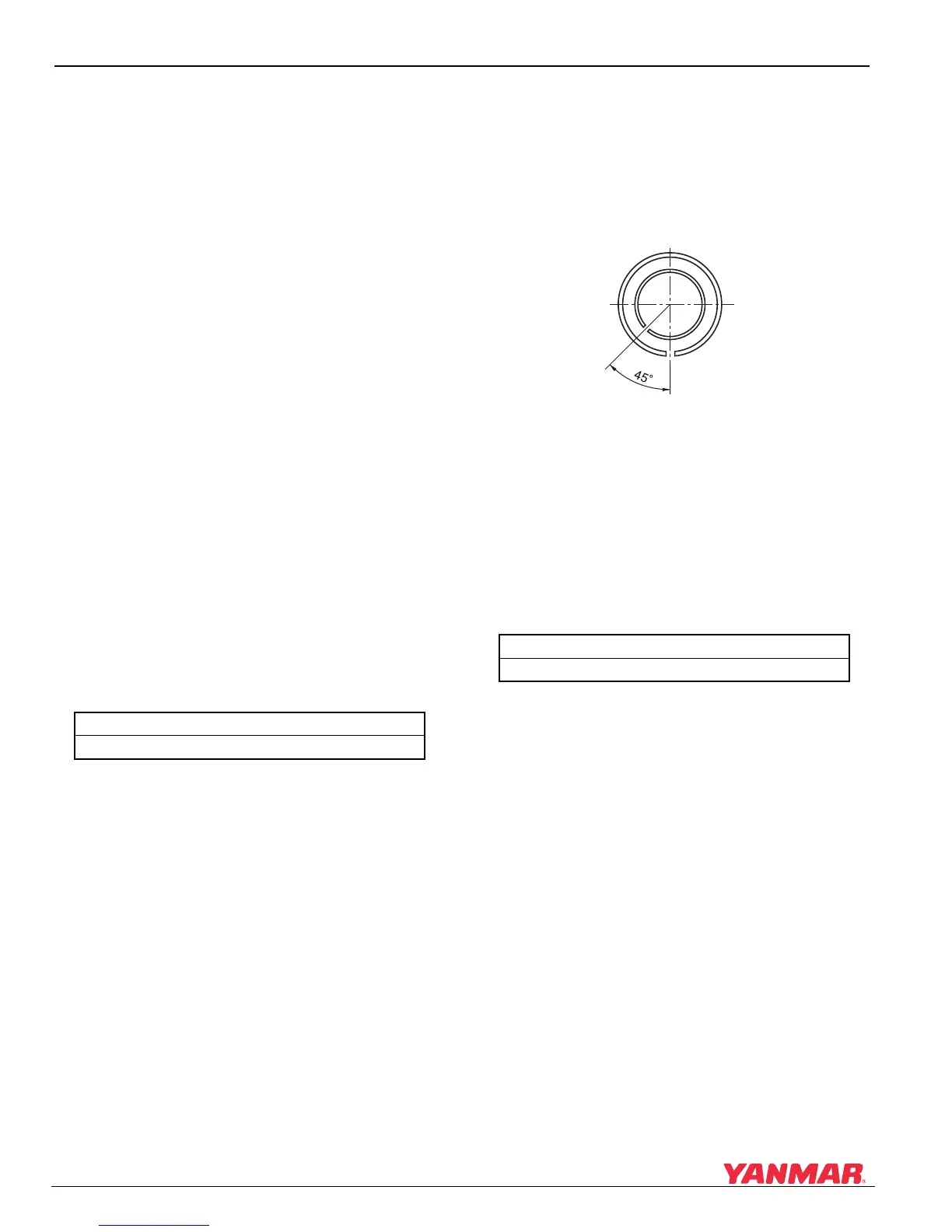
3. Adjust the gap in the seal rings to match
(Figure 9-13).
Figure 9-13
Figure 9-13
1 – Oil Inlet
2 – Position the ring closest to the compressor.
4. Apply Three Bond
®
No. 1207 sealant to the
turbine-side flange face of the seal plate and
mount to the bearing housing.
5. Apply Three Bond
®
No. 1207 to the spots
shown in Figure 9-13, (1).
Thrust Bearing Bolt Torque
13 ± 1 kgf·cm (6.1 lb-in)
Thickness of Sealant
0.1 - 0.2 mm (0.003 - 0.007 in.)
45q
(1)
(2)
0006251

 Loading...


