ENGINE
Assembling the Engine and Components
12/05
6LY3 Service Manual
5-75
© 2007 Yanmar Marine International
4. Check the fit and alignment of all assemblies
and tighten in the sequence shown in
Figure 5-128.
NOTICE: NEVER allow oil or other lubricant to
remain on the mating surface of the silencer
(Figure 5-129, (2)), hose or turbocharger
(Figure 5-129, (1)), as the assembly will come
apart during engine operation.
Figure 5-129
Figure 5-129
1 – Turbocharger
2–Silencer
3–Flanges
5. Thoroughly degrease the silencer flange, the
inside of the hose and the turbocharger flange.
6. Assemble the components and tighten the hose
bands to the following specified torque value.
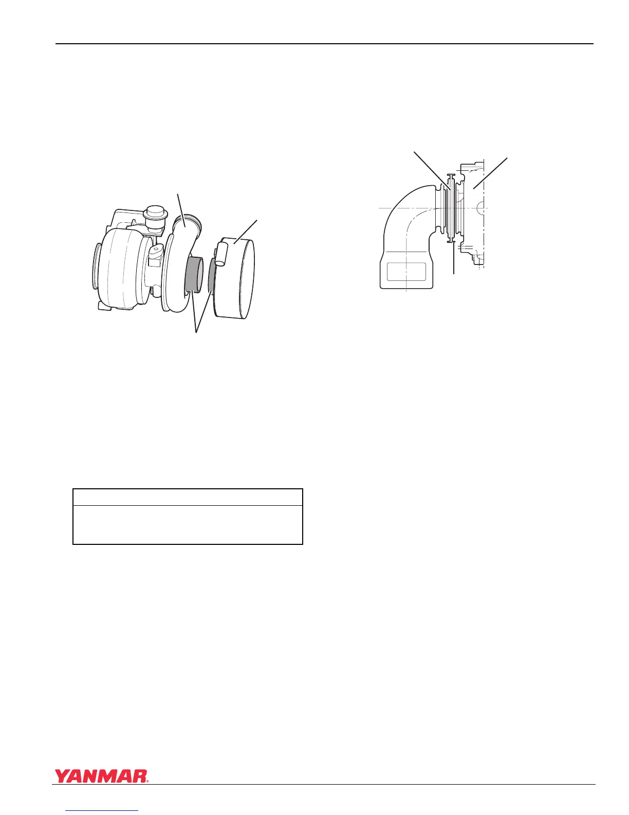
Installing the Mixing Elbow
Install the mixing elbow (Figure 5-130, (4)) to the
turbocharger (Figure 5-130, (2)) with the gasket
(Figure 5-130, (1)) and the V-band
(Figure 5-130, (3)).
Figure 5-1 30
Figure 5-130
1 – Gasket
2 – Turbocharger
3–V-Band
4 – Mixing Elbow
Hose Band Torque
3 ± 0.5 N·m
(0.3 ± 0.05 kgf·m)
(2.2 ± 0.3 lb-ft)
0005832
(2)
(3)
(1)
0005833
(2)
(1)
(3)
(4)

 Loading...


