FUEL SYSTEM
Fuel Injection Pump / Governor / Timer
6-14 6LY3 Service Manual
© 2007 Yanmar Marine International
Removing the Fuel Injection Pump
1. Set the crankshaft at 29° BTDC (Before Top
Dead Center) on the compression stroke of the
No. 6 cylinder. NOTICE: Both intake / exhaust
values are closed on the compression stroke.
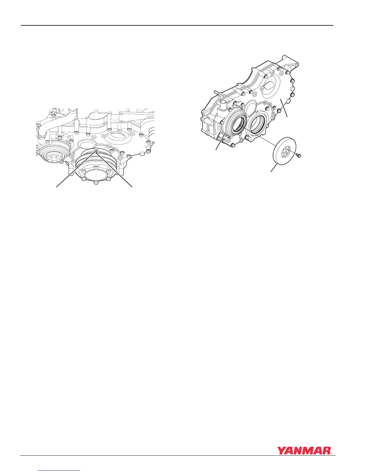
2. At 29° BTDC, the index marks on the V-pulley
(Figure 6-9, (2)) and drive shaft housing cover
(Figure 6-9, (1)) should align.
Figure 6-9
Figure 6-9
1 – Index Mark (Drive Shaft Housing Cover)
2 – Index Mark (V-Pulley)
3. Remove the fuel injection lines, supply lines
and cap the ends to keep dirt out.
4. Remove the damper (Figure 6-10, (3)) on the
fuel injection pump.
Figure 6-10
Figure 6-10
1 – Timer Cover
2 – Drive Shaft Housing Cover
3–Damper
(1)
(2)
0005672
0005673
(1)
(3)
(2)

 Loading...


