FUEL SYSTEM
Electronic Control System
6-36 6LY3 Service Manual
© 2007 Yanmar Marine International
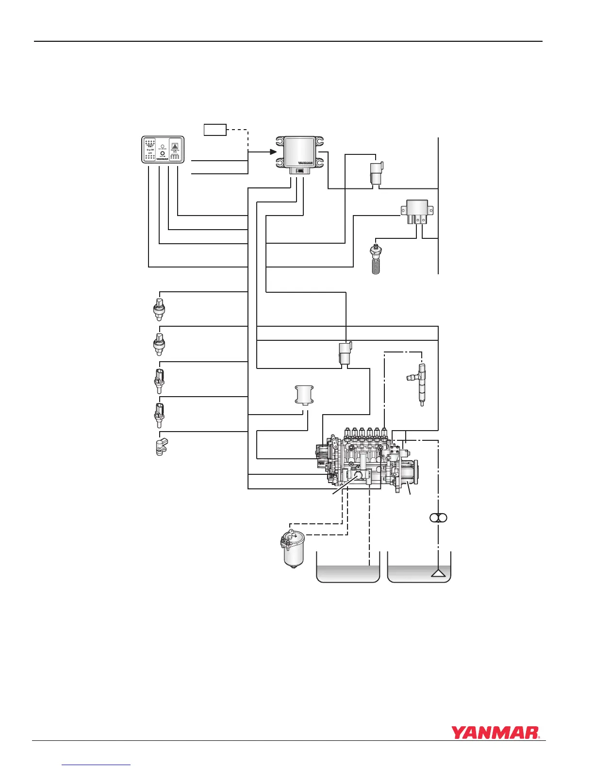
Engine Control System Diagram
The engine control system diagram is shown in Figure 6-46. The ECU controls the fuel injection quantity
and injection timing based on information such as engine operation (throttle, gear shift, control panel) and
engine condition (temperature, pressure, etc.).
Figure 6-46
Figure 6-46
Rocker switch panel
Throttle signal
Neutral signal
Emergency stop
Switch
Start Switch
Ignition Switch
Backup throttle sensor
CAN
ECU
Intake air pressure sensor
Oil pressure sensor
Water temperature sensor
Oil temperature sensor
Crank angle sensor
Main relay
Air heater relay
Rack actuator relay
Timer solenoid advance
Timer solenoid retard
Electronic governor
Rack position
amplifier
Rack position
sensor
Camshaft speed
sensor
Fuel temperature sensor
Fuel injection pump
Injection
nozzle
Fuel feed pump
Oil pump
Oil sump
Fuel tank
Fuel filter
Intake air heater
+B
Electro-hydraulic
timer
YDT
0005710

 Loading...


