STARTER
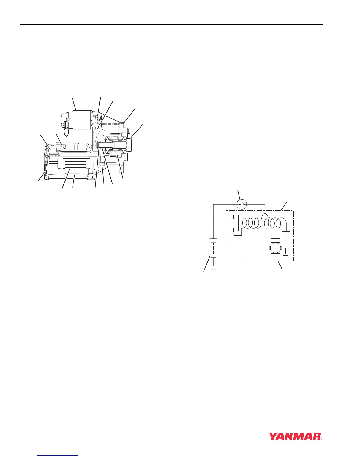
Starter Components and Functions
10-8 6LY3 Service Manual
© 2007 Yanmar Marine International
Starter Operation
When the starting switch is turned on, the solenoid
extends and the pinion gear is pushed to engage
the teeth of the flywheel. At the same time, the
starter motor spins. This rotates the flywheel of the
engine until it starts.
Figure 10-3
Figure 10-3
1 – Magnetic Switch (Solenoid)
2 – Torsion Spring
3–Shift Lever
4 – Drive Shaft Housing
5 – Pinion
6–Clutch
7 – Shift Return Spring
8–Bearing
9 – Pinion Stop
10–Yoke
11 – Armature
12 – Rear Cover
13–Brush Assembly
14 – Field Coil
Starter Wiring Diagram
1. When the starting switch is engaged, the core
of the switch is energized. This extends the
contact end of the solenoid to close the circuit
between the battery and the starter motor. As
the core extends to close electrical contacts on
one end, the other end of the solenoid core
moves a lever that pushes the pinion gear
against spring pressure into engagement with
the teeth of the flywheel ring gear.
2. With battery power being supplied to the
armature of the starter motor, the pinion gear is
driven to rotate.
3. When the starting switch is released, the
solenoid returns to its normal state. This breaks
contact between the armature of the starter
motor and the battery, the pinion gear is
retracted by return spring pressure.
Figure 10-4
Figure 10-4
1 – Starting Switch
2 – Magnetic Switch
3 – Starting Motor
4–Battery
0006304
(1) (2)
(3)
(4)
(5)
(6)
(7)
(8)
(9)
(10)(11)
(12)
(13)
(14)
B
M
S
Mag
Mag
0006305
(2)
(1)
(3)
(4)

 Loading...


