ELECTRICAL AND ECU
Fuse, Relay and Harness Components
12-16 6LY3 Service Manual
© 2007 Yanmar Marine International
FUSE, RELAY AND HARNESS
COMPONENTS
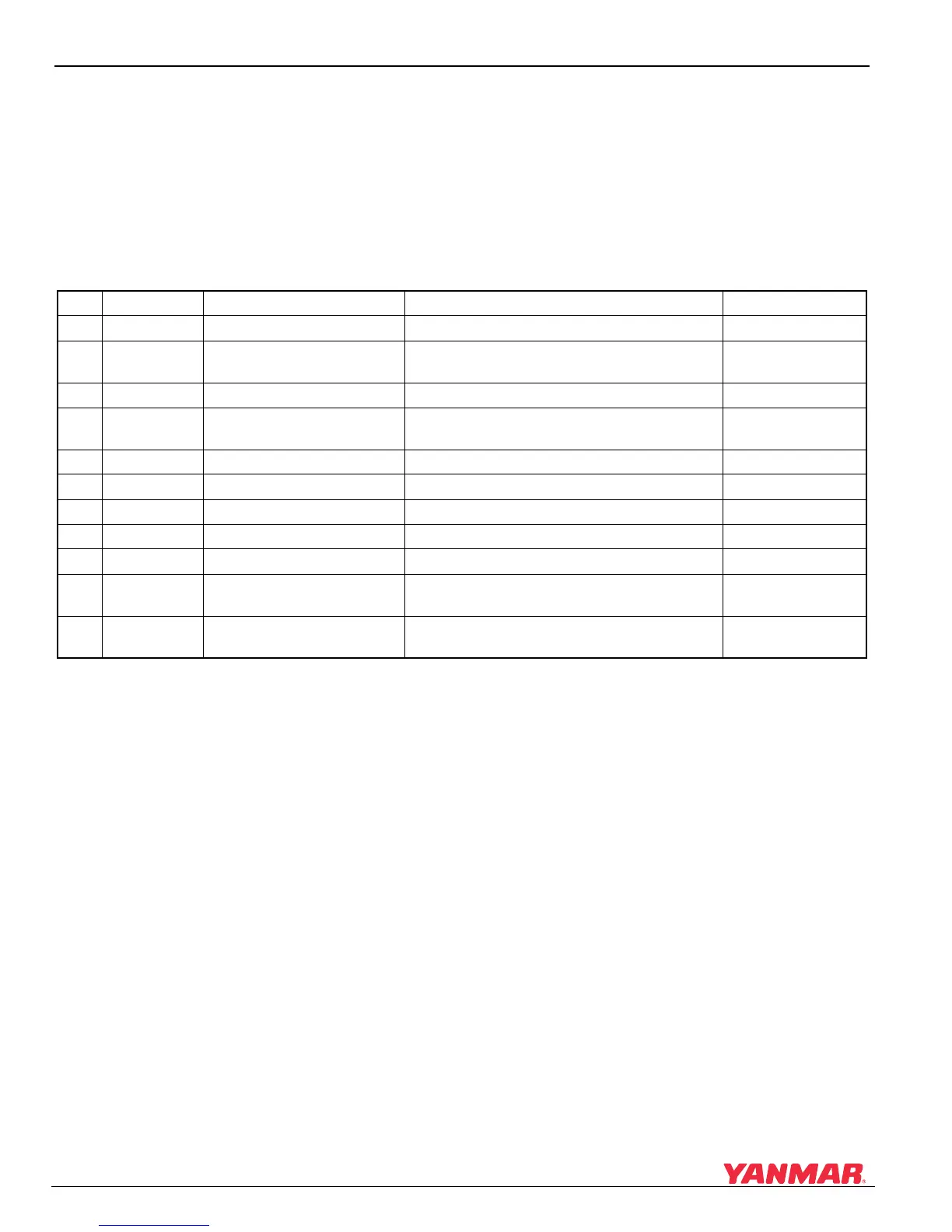
When a short-circuit occurs, the electrical system is
protected by a fuse. See Troubleshooting on
page 13-1. All the fuses for the 6LY3 are shown in
the table below.
Fuse Chart
No. Fuse Size Application Fuse Location Part No.
1 10A AUX POWER Fuse box 198535-52120
2 10A
IGNITION PANEL
(Switch panel)
Fuse box 198535-52120
3 20A ECU Fuse box 198535-52140
4 10A
IGNITION SIG
(Switch ON signal)
Fuse box 198535-52120
5 5A YDT Fuse box 198535-52110
6 250A Air Heater “A” Below exhaust manifold 119578-77150
7 250A Air Heater “B” Below exhaust manifold 119578-77150
8 150A ALTERNATOR Below exhaust manifold 119578-77090
9 50A STARTER RELAY Below exhaust manifold 119578-77080
10 5A
IGNITION SIG 1st Station
(Switch ON signal)
Rocker switch panel (1st Station) 170203-91930
11 5A
IGNITION SIG 2nd Station
(Switch ON signal)
Rocker switch panel (2nd Station) 170203-91930

 Loading...


