ENGINE
Assembling the Engine and Components
5-76 6LY3 Service Manual
© 2007 Yanmar Marine International
Installing the Oil Lines for the Fuel
Injection Pump
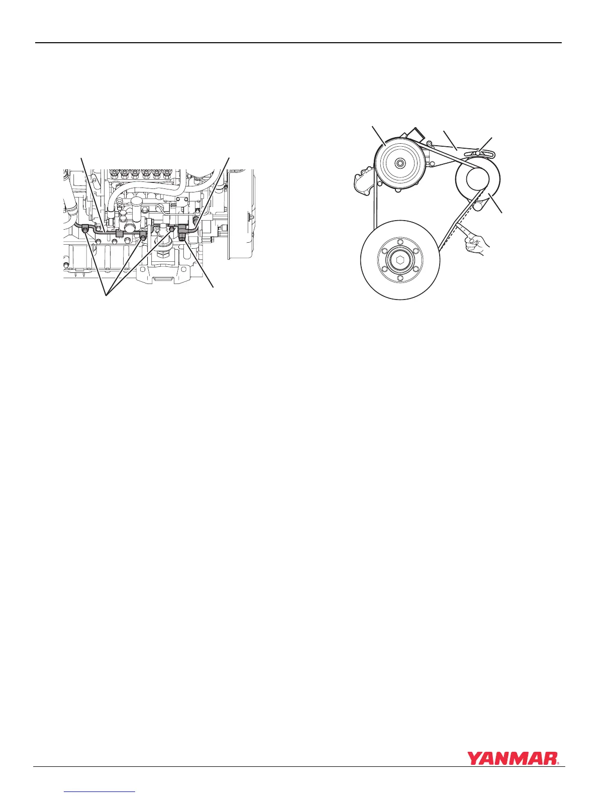
1. Fit oil line “A” (Figure 5-131, (1)) between the
pressure regulating valve, timer and fuel
injection pump.
Figure 5-131
Figure 5-131
1 – Oil Line “A”
2 – Oil Line “B”
3 – Overflow Valve
4 – Steady Brace and M8 Bolts
2. Install the supporting brackets as shown in
Figure 5-131.
3. Apply seal washers to the pipe joint bolts.
4. Tighten the overflow valve (Figure 5-131, (3))
for oil line “A” and oil line “B” (Figure 5-131, (2))
at the timer inlet.
Installing the Alternator
1. Install the adjuster (Figure 5-132, (2)) on the
coolant pump (Figure 5-132, (1)).
Figure 5-132
Figure 5-132
1–Coolant Pump
2 – Adjuster
3 – Adjuster Bolt
4–Alternator
5 – Check Tension
6 – Deflection 8-10 mm (approximately 3/8 in.)
7–V-Belt
2. Torque the adjuster bolts (Figure 5-132, (3)) to
the specified values.
3. Install the alternator (Figure 5-132, (4)).
4. Adjust the V-belt (Figure 5-132, (7)) tension as
shown in Adjust the V-Belt Tension or Replace
V-Belt on page 4-14 and tighten all the bolts to
the specified values.
Installing the Starter Motor
1. Install the starter motor to the flywheel housing.
2. Tighten the bolts to the specified torque value.
0005834
(1) (2)
(3)
(4)
0005835
(4)
(5)
(6)
(7)
(1)
(2)
(3)

 Loading...


