TURBOCHARGER
Inspecting the Turbocharger
12/05
6LY3 Service Manual
9-17
© 2007 Yanmar Marine International
3. Measure the width of the seal ring grooves for
the oil thrower at G1 and G2 (Figure 9-7).
4. Measure the width of the thrust bearing
(Figure 9-8, (1)).
Figure 9-8
Figure 9-8
1 – Thrust Bearing Width
2 – Thrust Bearing
NOTICE: If any of these dimensions is beyond
the specified limits, replace the entire thrust
bearing.
Floating Bearings
1. Inspect the floating bearing for any abnormal
wear patterns, scratches or discoloration.
Replace the floating bearings if any
discrepancies are found.
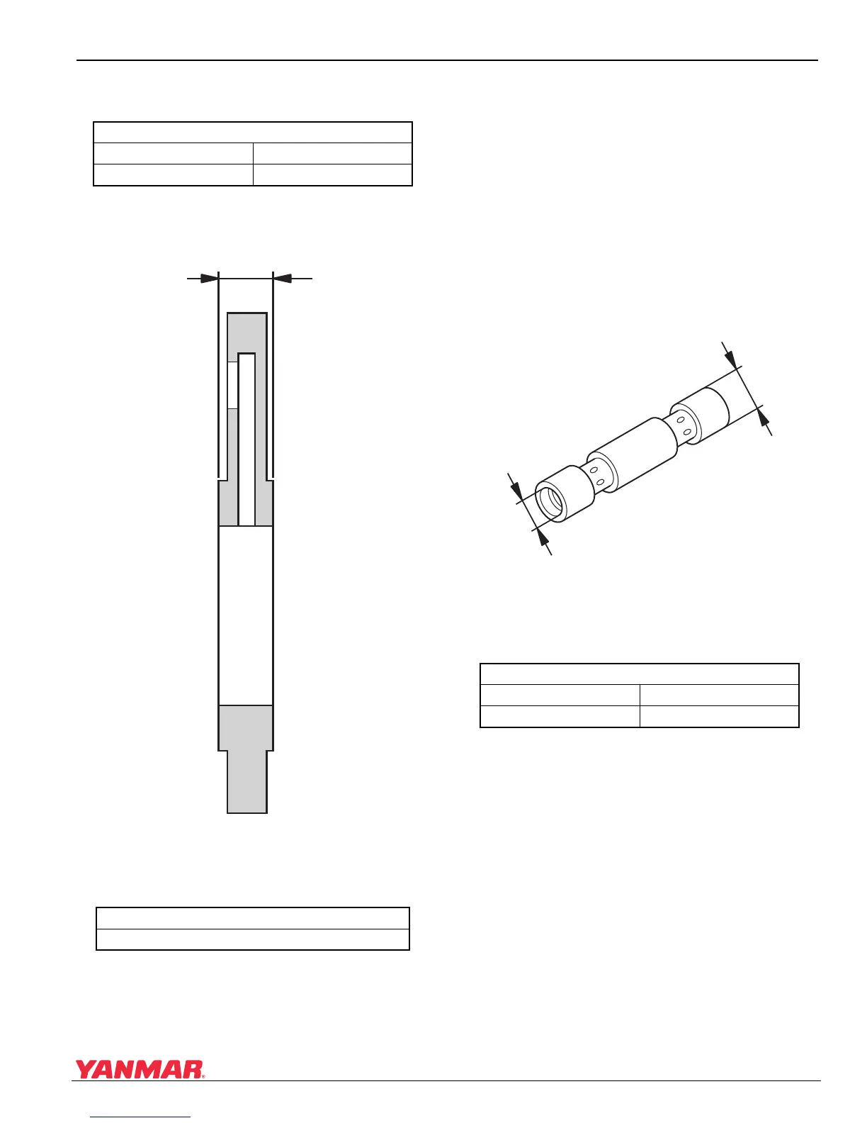
2. Measure the inside (Figure 9-9, (1)) and
outside (Figure 9-9, (2)) diameters. If worn
beyond limits, replace the bearings with new
ones.
Figure 9-9
Figure 9-9
1 – Inside Diameter
2 – Floating Bearing
3 – Outside Diameter
Oil Thrower Seal Ring Grooves
Groove G1 Limit: 1.75 mm (0.068 in.)
Groove G2 Limit: 1.52 mm (0.059 in.)
Thrust Bearing Width
Limit: 4.48 mm (0.176 in.)
(1)
(2)
0005899
Floating Bearing
Inside Diameter Limit: 16.98 mm (0.668 in.)
Outside Diameter Limit: 12.36 mm (0.486 in.)
(1)
(2)
(3)
0005900

 Loading...


