3.1 Standard Connection Diagram
YASKAWA ELECTRIC TOEP C710616 50B YASKAWA AC Drive - A1000 6-Phase/12-Pulse Input Installation Guide 29
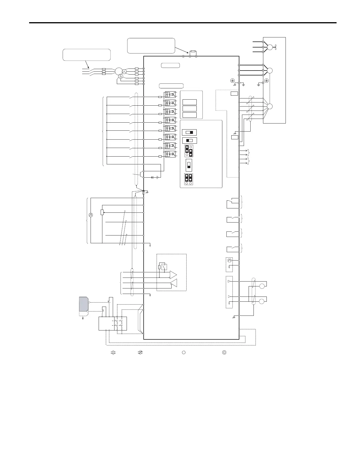
Figure 3.1
Figure 3.1 Drive Standard Connection Diagram (example: CIMR-A4T0058)
<1> Set up a thermal relay sequence to disconnect drive main power in the event of an overheat condition on the dynamic braking option.
<2> Set L8-55 to 0 to disable the protection function of the built-in braking transistor of the drive when using an optional regenerative converter or
dynamic braking option. Leaving L8-55 enabled may cause a braking resistor fault (rF). Additionally, disable Stall Prevention (L3-04 = 0)
when using an optional regenerative converter, regenerative or braking units, or dynamic braking option. Leaving L3-04 enabled may prevent
the drive from stopping within the specified deceleration time.
<3> Supplying power to the control circuit separately from the main circuit requires a 24 V power supply (option).
<4> This figure illustrates an example of a sequence input to S1 through S8 using a non-powered relay or an NPN transistor. Install the wire jumper
between terminals SC-SP for Sink mode, between SC-SN for Source mode, or leave the jumper out for external power supply. Never short
terminals SP and SN, as it will damage the drive.
+
㧙
+
+
Terminals -, +3, B1, and B2 are
for power option connections.
Never connect power supply lines
to these terminals
+
㧙
+
+
+
㧙
S1
S2
S3
S4
S5
S6
S7
MP
DM
DM
RP
A
1
A2
A3
0
V
AC
R
R
S
S
IG
H
1
H2
HC
Drive
B1 B2
2 k
S
8
SC
0 V
0 V
AC
FM
AM
AC
E (G)
S
1
S2
<1> <2>
<10>
<6>
<11>
<12>
<7>
<9>
<6>
<4>
<3>
+
24 V
+
V
MA
M
1
M2
MB
MC
Forward Run / Stop
Reverse Run / Stop
External fault
Fault reset
Multi-speed step 1
Multi-speed step 2
External Baseblock
Jog speed
Multi-function
digtial inputs
(default setting)
Sink / Source mode
selection wire jumper
(default: Sink)
CN5-C
CN5-B
CN5-A
Option board
Pulse Train Input (max 32 kHz)
Shield ground terminal
Fuse
Multi-function
analog/pulse
train inputs
Power supply +10.5 Vdc, max. 20 mA
Analog Input 1 (Frequency Reference Bias)
-10 to +10 Vdc (20 k )
Analog Input 2 (Frequency Reference Bias)
-10 to +10 Vdc (20 k )
0 or 4 to 20 mA (250 )
Analog Input 3 / PTC Input (Aux. frequency
reference)
-10 to +10 Vdc (20 k )
−
V
Power supply, -10.5 Vdc, max. 20 mA
Safety
switch
MEMOBUS/Modbus
comm. RS485/422
max. 115.2 kBps
Safe Disable inputs
Wire
jumper
Open
Safety relay /
controller
Termination resistor
(120 , 1/2 W)
DIP
Switch S2
Fault relay output
250 Vac, max. 1 A
30 Vdc, max 1 A
(Minimum rating, 5 Vdc 10 mA)
Multi-function relay output (During Run)
250 Vac, max. 1 A
30 Vdc, max 1 A
(Minimum rating, 5 Vdc 10 mA)
Multi-function pulse train output
(Output frequency)
0 to 32 kHz (2.2 k )
Multi-function analog output 1
(Output frequency)
-10 to +10 Vdc (2mA)
or 4 to 20 mA
EDM (Safety Electronic Device Monitor)
Main Circuit
Control Circuit
shielded line
twisted-pair shielded line
main circuit terminal
control circuit terminal
M3
M4
Multi-function relay output (Zero Speed)
250 Vac, max. 1 A
30 Vdc, max 1 A
(Minimum rating, 5 Vdc 10 mA)
M5
M6
Multi-function relay output (Speed Agree 1)
250 Vac, max. 1 A
30 Vdc, max 1 A
(Minimum rating, 5 Vdc 10 mA)
SP
SN
<8>
AMFM
V
I
V
I
DIP Switch S1
A2 Volt/Curr. Sel
DIP Switch S4
A3 Analog/PTC
Input Sel
PTC
AI
Off
On
DIP Switch S2
Term. Res. On/Off
Jumper S3
H1, H2
Sink/Source Sel.
Jumper S5
AM/FM Volt./Curr.
Selection
Terminal board
jumpers and switches
FM
+
㧙
AM
<5>
<13>
Ω
Ω
Ω
Ω
Ω
Ω
<12>
Multi-function analog output 2
(Output current)
-10 to +10 Vdc (2mA)
or 4 to 20 mA
Three-Phase
Power Supply
380 to 480 V
50/60 Hz
<14>
<5>
A+
A
B
Z
B+
Z+
a+
a-
b+
b-
z+
z-
FE
IP
IG
TB1
SD
TB2
B track monitor
A track monitor
M
U/T
1
V/T2
W/T
U
FU
FV
FW
V
W
3
Ground
Cooling fan
PG
M
PGX3
connectors
(option)
Wiring sequence should shut off
power to the drive when a fault
output is triggered.
Ω
Fuse
R/L1
S/L2
T/L3
R1/L11
S1/L21
T1/L31
R
S
T
Main
Switch
Braking Resistor Unit
(LKEB Type)
(option)
U1
V1
W1
W2
V2
U2

 Loading...


