3.4 Main Circuit Wiring
38 YASKAWA ELECTRIC TOEP C710616 50B YASKAWA AC Drive - A1000 6-Phase/12-Pulse Input Installation Guide
Wire Gauges and Tightening Torque
Use Table 3.2 to select the appropriate wires and crimp terminals.
Wire gauges listed in the tables are for use in the United States.
Note: 1. Wire gauge recommendations based on drive continuous current ratings (ND) using 75°C 600 Vac vinyl-sheathed wire assuming
ambient temperature within 40°C and wiring distance less than 100 m.
2. Terminals +3 and – are for connecting optional devices such as a braking unit. Do not connect other nonspecific devices to these
terminals.
• Consider the amount of voltage drop when selecting wire gauges. Increase the wire gauge when the voltage drop is
greater than 2% of motor rated voltage. Ensure the wire gauge is suitable for the terminal block. Use the following
formula to calculate the amount of voltage drop:
Line drop voltage (V) = × wire resistance (Ω/km) × wire length (m) × current (A) × 10
-3
• Refer to instruction manual TOBP C720600 00/TOBP C720600 01 for braking unit option or braking resistor option
wire gauges.
• Use terminal +3 and the negative terminal when connecting a braking unit option.
• Do not connect the regenerative converter or the regenerative unit to the 6-Phase/12-Pulse A1000 drive.
•Refer to UL Standards Compliance on page 64 for information on UL compliance.
Yaskawa recommends using closed-loop crimp terminals on all drive models. UL/cUL approval requires the use of
closed-loop crimp terminals when wiring the drive main circuit terminals. Use only the tools recommended by the
terminal manufacturer for crimping. Refer to Closed-Loop Crimp Terminal Size on page 65 for closed-loop crimp
terminal recommendations.
The wire gauges listed in Table 3.2 are Yaskawa recommendations and are based on the 6-Phase input current ratings
specified in Table C.1. Refer to local codes for proper wire gauge selections.
6-Phase/12-Pulse Input 400 V Class
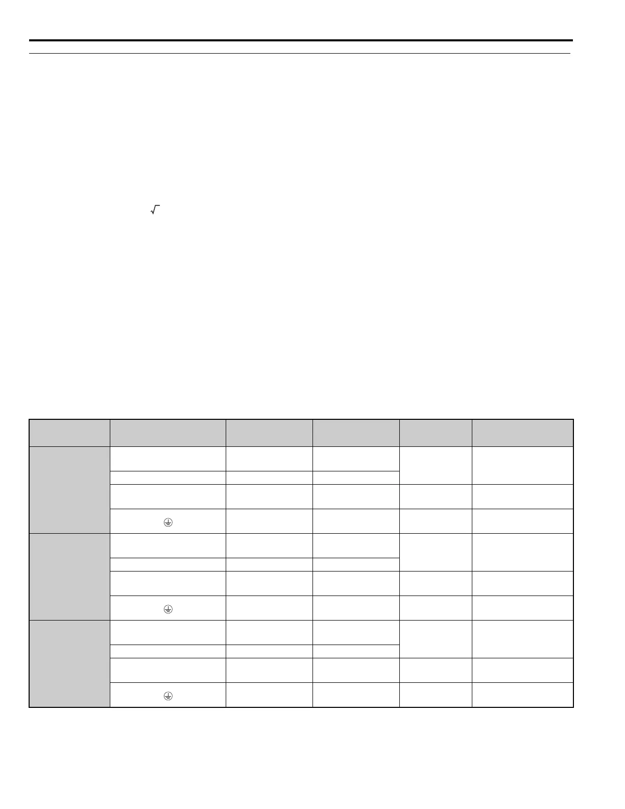
Table 3.2 Wire Gauge and Torque Specifications
Model
CIMR-A
Terminal
Recomm. Gauge
AWG, kcmil
Wire Range
AWG, kcmil
Screw
Size
Tightening Torque
N-m (ib.in.)
4T0058
R/L1, S/L2, T/L3
R1/L11, S1/L21, T1/L31
8 10 to 1/0
M8
9 to 11
(79.7 to 97.4)
U/T1, V/T2, W/T3 4 10 to 1/0
B1, B2 – 14 to 10 M4
1.1 to 1.2
(9.74 to 10.6)
68 to 6M8
9 to 11
(79.7 to 97.4)
4T0072
R/L1, S/L2, T/L3
R1/L11, S1/L21, T1/L31
8 10 to 1/0
M8
9 to 11
(79.7 to 97.4)
U/T1, V/T2, W/T3 3 10 to 1/0
B1, B2 – 14 to 10 M4
1.1 to 1.2
(9.74 to 10.6)
66M8
9 to 11
(79.7 to 97.4)
4T0088
R/L1, S/L2, T/L3
R1/L11, S1/L21, T1/L31
6 6 to 1/0
M8
9 to 11
(79.7 to 97.4)
U/T1, V/T2, W/T3 2 6 to 1/0
–, +3 – 12 to 2 M6
2.5 to 3.0
(22.1 to 26.6)
46 to 4M8
9 to 11
(79.7 to 97.4)
3

 Loading...


