48 YASKAWA ELECTRIC TOEP C710616 50B YASKAWA AC Drive - A1000 6-Phase/12-Pulse Input Installation Guide
5.2 Connecting Peripheral Devices
5.2 Connecting Peripheral Devices
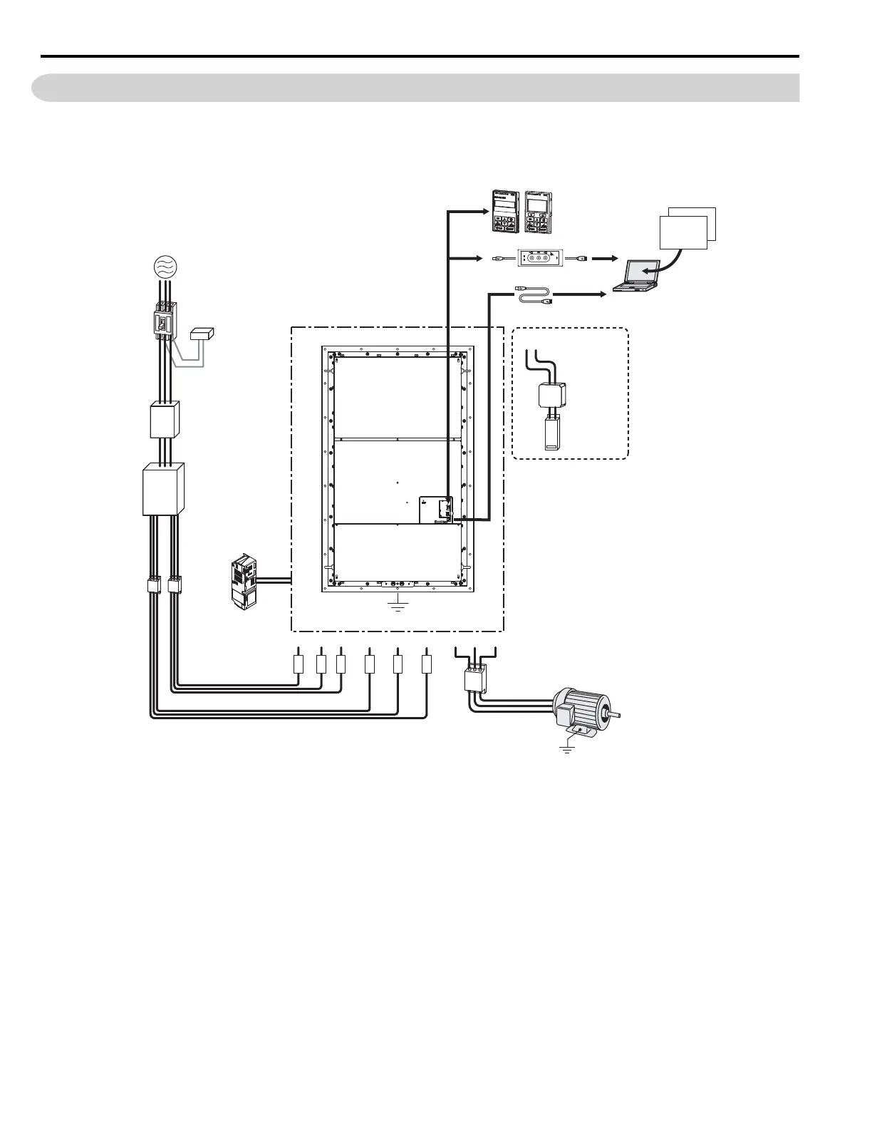
Figure 5.1 illustrates how to configure the drive and motor to operate with various peripheral devices.
Refer to the specific manual for the devices shown below for more detailed installation instructions.
Figure 5.1 Connecting Peripheral Devices
Note: If the drive is set to trigger a fault output when the fault restart function is activated (L5-02 = 1), then a sequence to interrupt
power when a fault occurs will turn off the power to the drive while the drive attempts to restart. The default setting for L5-02 is 0
(fault output active during restart).
<1> With each of the output windings phase shifted by 30 electrical degrees.
C
op
y
Ver
ify
R
ea
d
LOCK
YASKAWA
JVOP-181
USB Copy Unit
COM ERR
PC
DriveWizard X
Engineering Software Tools
DriveWorksEZ
Power
Supply
Line
Breaker
(MCCB)
or
Leakage
Breaker
Surge
Absorber
Input Side
Noise Filter
Braking Unit
(CDBR Type)
Braking
Resistor Unit
(LKEB Type)
Output Side
Noise Filter
Drive
Ground
+3 -
Motor
U/T1 V/T2 W/T3R1/L11
24 V Control
Power Supply
Unit
S1/L21 T1/L31R/L1
Fuse
S/L2 T/L3
Ground
USB Copy Unit
USB Type-AB Cable
(sold separately)
LED Operator/LCD Operator
6-Phase/12-Pulse
Isolation Transformer
or
Hybrid 6-Phase
Topology
3-Phase Line Monitor
<1>

 Loading...


