3.2 Main Circuit Connection Diagram
YASKAWA ELECTRIC TOEP C710616 50B YASKAWA AC Drive - A1000 6-Phase/12-Pulse Input Installation Guide 31
3.2 Main Circuit Connection Diagram
Refer to diagrams in this section when wiring the main circuit of the drive. Connections vary based on drive capacity.
NOTICE: Do not use the negative DC bus terminal “–” as a ground terminal. This terminal is at high DC voltage potential. Improper
wiring connections could damage the drive.
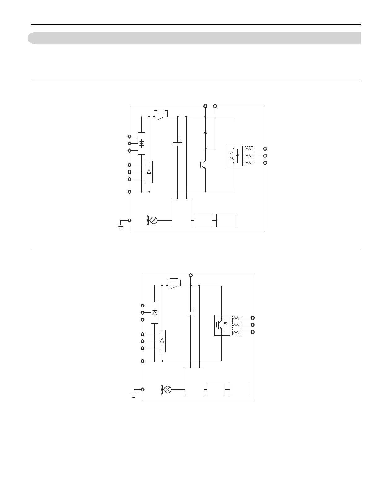
6-Phase/12-Pulse Input 400 V Class (CIMR-A4T0058, 0072)
Figure 3.2
Figure 3.2 A1000 6-Phase/12-Pulse Drive Internal Main Circuit Diagram (CIMR-A4T0058, 0072)
6-Phase/12-Pulse Input 400 V Class (CIMR-A4T0088 to 0139)
Figure 3.3
Figure 3.3 A1000 6-Phase/12-Pulse Drive Internal Main Circuit Diagram (CIMR-A4T0088 to 0139)
R1/L11
S1/L21
T1/L31
Gate
Board
Control
Board
Operator
B1
R/L1
S/L2
T/L3
–
U/T1
V/T2
W/T3
Relay
Current
Sensor
B2
Gate
Board
Control
Board
Operator
+3
R/L1
S/L2
T/L3
R1/L11
S1/L21
T1/L31
–
U/T1
V/T2
W/T3
Relay
Current
Sensor

 Loading...


