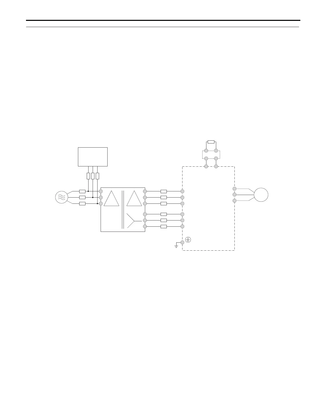
3.2 Main Circuit Connection Diagram
YASKAWA ELECTRIC TOEP C710616 50B YASKAWA AC Drive - A1000 6-Phase/12-Pulse Input Installation Guide 33
6-Phase/12-Pulse Rectification
Installing a Transformer
Install a 6-Phase/12-Pulse isolation transformer with output windings phase shifted by 30 electrical degrees or install a
Hybrid 6-Phase topology on the power supply.
Installing a 3-Phase Line Monitor
Yaskawa requires installation of a 3-Phase line monitor to protect the drive in the event of an input line phase loss.
The 3-Phase line monitor must be installed on the primary circuit of the 6-Phase/12-Pulse transformer and connected to
the A1000 drive to remove the RUN command when a phase loss condition occurs.
The A1000 power circuit may be damaged during a phase-loss condition if a 3-Phase line monitor is not properly
installed.
Connection Diagram
Figure 3.5 Main Circuit Terminal Connections
<1> A braking resistor can be connected to the B1 and B2 terminals on the CIMR-A4T0058 and 0072 drives.
<2> A braking unit cannot be connected to the CIMR-A4T0058 and 0072 drives.
U/T1
V/T2
W/T3
R/L1
S/L2
T/L3
R1/L11
S1/L21
T1/L31
Braking Unit (CDBR Type)
(option)
<2>
Braking Resistor Unit (LKEB Type)
(option)
<1>
Motor
+3
㧙
Main Circuit
Power Supply
6-Phase/12-Pulse
Isolation Transformer
3-Phase Line Monitor
Fuse
Fuse
Fuse

 Loading...


