3.5 Wiring Checklist
YASKAWA ELECTRIC TOEP C710616 50B YASKAWA AC Drive - A1000 6-Phase/12-Pulse Input Installation Guide 41
3.5 Wiring Checklist
No. Item Page(s)
Drive, Peripherals, Option Cards
1 Check drive model number to ensure receipt of correct model. 10
2 Make sure you have the correct braking resistors, noise filters, and other peripheral devices. –
3 Check that any installed option cards are the correct model. –
Installation Area and Physical Setup
4 Ensure that the area surrounding the drive complies with specifications. 14
Power Supply Voltage, Output Voltage
5 The voltage from the power supply should be within the input voltage specification range of the drive. –
6 The voltage rating for the motor should match the drive output specifications.
10
7 Verify that the drive is properly sized to run the motor.
Main Circuit Wiring
8 Confirm proper branch circuit protection as specified by national and local codes. 28
9
Properly wire the power supply to drive terminals R/L1, S/L2, T/L3, R1/L11, S1/L21, and T1/L31.
Note: Confirm that a 6-Phase/12-Pulse isolation transformer with each of the output windings phase shifted by
30 electrical degrees or a Hybrid 6-Phase topology is installed on the power supply.
31
10
Properly wire the drive and motor together.
The motor lines and drive output terminals U/T1, V/T2, and W/T3 should match in order to produce the
desired phase order. If the phase order is incorrect, the drive will rotate in the opposite direction.
–
11 Use 600 Vac vinyl-sheathed wire for the power supply and motor lines. 38
12
Use the correct wire gauges for the main circuit. Refer to Wire Gauges and Tightening Torque on page 38.
38
• Consider the amount of voltage drop when selecting wire gauges. Increase the wire gauge when the voltage
drop is greater than 2% of motor rated voltage. Ensure the wire gauge is suitable for the terminal block. Use
the following formula to calculate the amount of voltage drop:
Line drop voltage (V) = × wire resistance (Ω/km) × wire length (m) × current (A) × 10
-3
• If the cable between the drive and motor exceeds 50 m, adjust the carrier frequency set to C6-02 accordingly.
13 Properly ground the drive. –
14
Tighten control circuit and grounding terminal screws. Refer to Wire Gauges and Tightening Torque on
page 38.
38
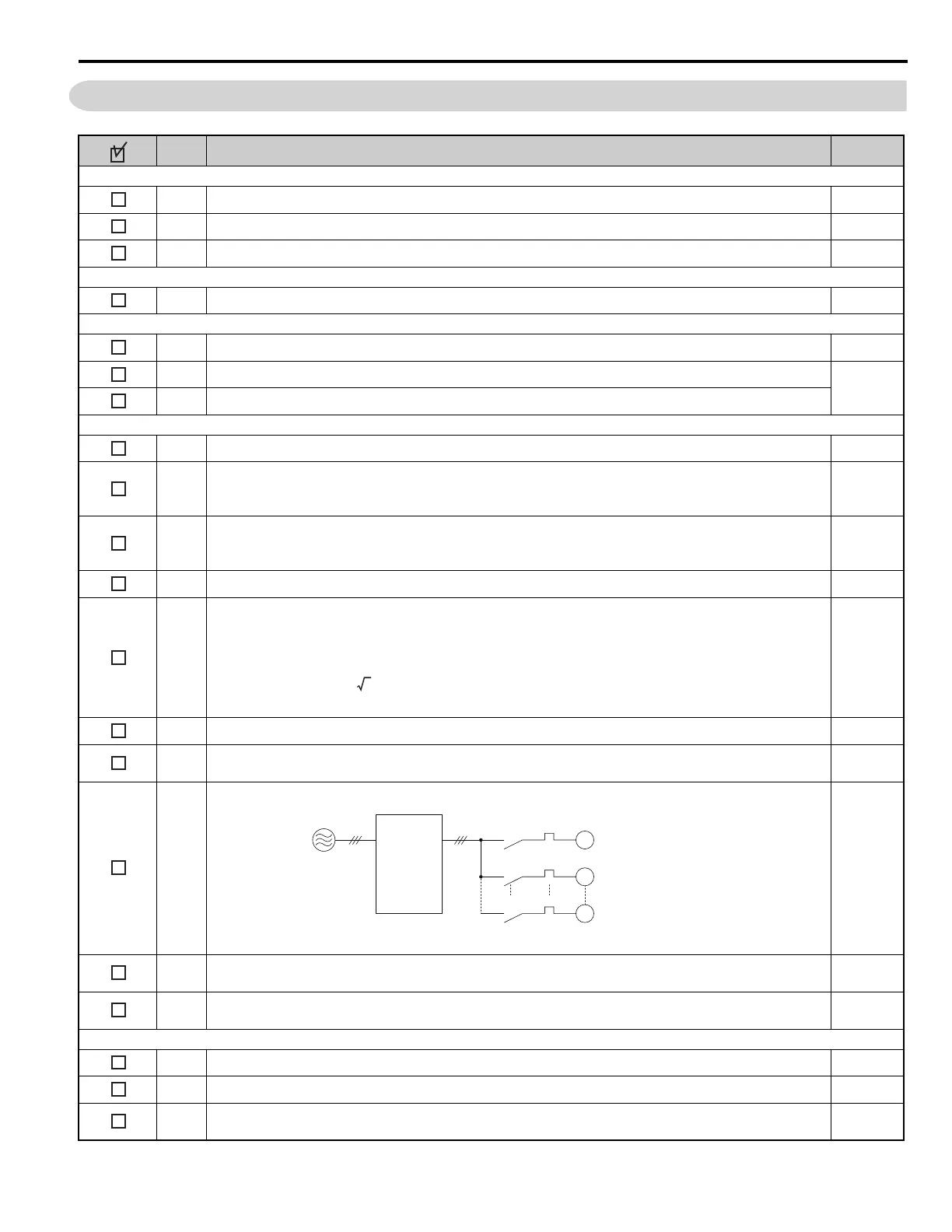
15
Set up overload protection circuits when running multiple motors from a single drive.
Note: Close MC1 - MCn before operating the drive. MC1 - MCn cannot be switched off during run.
–
16
Install a magnetic contactor when using a dynamic braking option. Properly install the resistor and ensure that
overload protection shuts off the main power supply using the magnetic contactor.
–
17
Verify phase advancing capacitors, input noise filters, or GFCIs are NOT installed on the output side of the
drive.
–
Control Circuit Wiring
18 Use twisted-pair line for all drive control circuit wiring. –
19 Ground the shields of shielded wiring to the GND terminal. –
20
For 3-Wire sequence, set parameters for multi-function contact input terminals S1 - S8, and wire control
circuits.
–
3
M1
OL1
OL2
OLn
MC1
MC2
MCn
M2
Mn
Drive
MC1 - MCn
OL 1 - OLn
... magnetic contactor
... thermal relay
Power supply

 Loading...


