3.4 Main Circuit Wiring
YASKAWA ELECTRIC TOEP C710616 50B YASKAWA AC Drive - A1000 6-Phase/12-Pulse Input Installation Guide 37
3.4 Main Circuit Wiring
This section describes the functions, specifications, and procedures required to safely and properly wire the main circuit
of the drive.
NOTICE: Do not solder the ends of wire connections to the drive. Soldered wiring connections can loosen over time. Improper wiring
practices could result in drive malfunction due to loose terminal connections.
NOTICE: Do not switch the drive input to start or stop the motor. Frequently switching the drive on and off shortens the life of the DC
bus charge circuit and the DC bus capacitors, and can cause premature drive failures. For the full performance life, refrain from
switching the drive on and off more than once every 30 minutes.
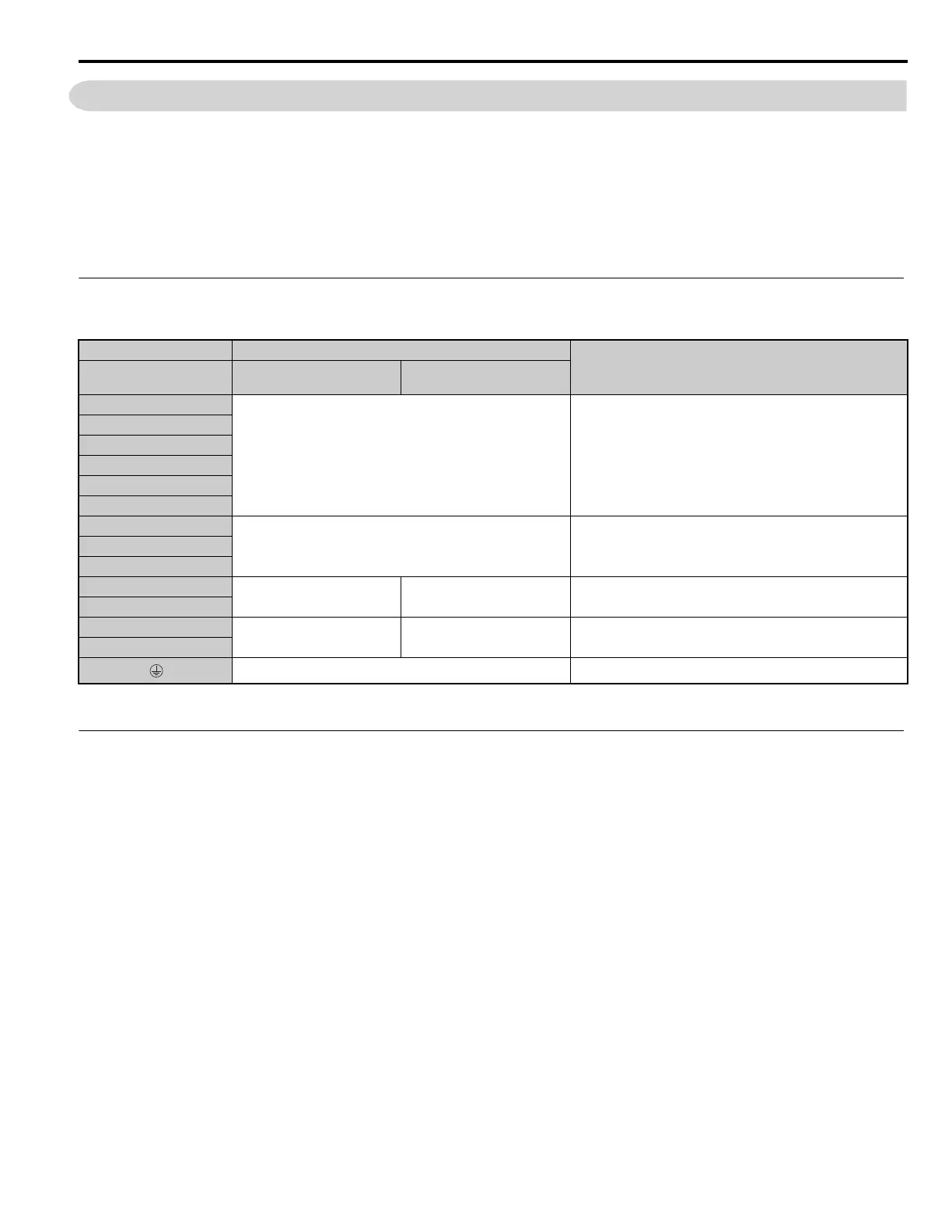
Main Circuit Terminal Functions
Table 3.1 Main Circuit Terminal Functions
Note: DC power supply input is not available for 6-Phase/12-Pulse Input models.
Main Circuit Fuses
The A1000 6-Phase/12-Pulse drive requires fuses to be installed on each of the 6 input phases between the 6-Phase/12-
Pulse transformer and the A1000 drive. To maintain standards compliance select fuses from Table C.1 . according to drive
model.
Terminal Type
Function
Model
CIMR-A
4T0058, 4T0072 4T0088 to 4T0675
R/L1
Main circuit power supply input Connects line power to the drive
S/L2
T/L3
R1/L11
S1/L21
T1/L31
U/T1
Drive output Connects to the motorV/T2
W/T3
B1
Braking resistor Not available
Available for connecting a braking resistor or a braking
resistor unit option
B2
–
Not available
Braking unit connection
(+3, –)
Only for connecting dynamic braking options
+3
10 Ω or less Grounding terminal

 Loading...


