6.3 MEMOBUS/Modbus Communications
232 YASKAWA SIEPC71061753C GA500 Technical Manual
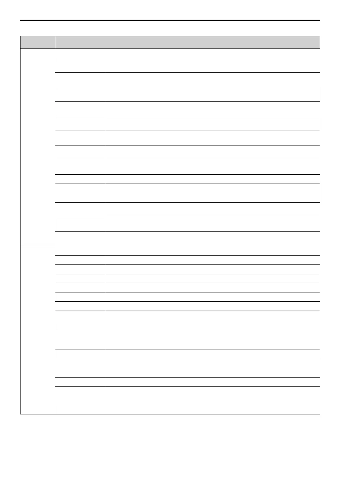
Table 6.16 Monitor Data for MEMOBUS/Modbus Communication
Register No.
(Hex.)
Description
0020
Drive Status 1
bit 0
During Run
1: During run, 0: During stop
bit 1
During Reverse
1: During reverse, 0: Forward run
bit 2
Drive ready
1: Ready, 0: Not ready
bit 3
Fault
1: Fault
bit 4
Data Setting Error
1: oPExx error
bit 5
MFDO (terminal MA/MB-MC)
1: ON, 0: OFF
bit 6
Multi-function photocoupler output 1 (terminal P1-C1)
1: ON, 0: OFF
bit 7
Multi-function photocoupler output 2 (terminal P2-C2)
1: ON, 0: OFF
bit 8 - B Reserved
bit C
SToF [Safe Torque OFF Hardware]
1: One of Safe Disable input 1 (terminal H1-HC) and Safe Disable input 2 (terminal H2-HC) is OFF (open) and the other is
ON (closed)
bit D
STo [Safe Torque OFF]
1: Both Safe Disable input 1 (terminal H1-HC) and Safe Disable input 2 (terminal H2-HC) are OFF (open)
bit E
ComRef status
1: Enabled
bit F
ComCtrl status
1: Enabled
0021
Fault Description 1
bit 0 oC [Overcurrent], GF [Ground Fault]
bit 1 ov [Overvoltage]
bit 2 oL2 [Drive Overload]
bit 3 oH1 [Heatsink Overheat], oH2 [External Overheat (H1-XX=B)]
bit 4 rH [Braking Resistor Overheat], rr [Dynamic Braking Transistor Fault]
bit 5 Reserved
bit 6 FbL [PID Feedback Loss], FbH [Excessive PID Feedback]
bit 7 EF0 [Option Card External Fault], EF1 to EF7 [External Fault]
bit 8
CPFxx [Hardware Fault]
Note:
Includes oFx.
bit 9
oL1 [Motor Overload], oL3, oL4 [Overtorque Detection 1/2], UL3, UL4 [Undertorque Detection 1/2]
bit A PGo [Encoder (PG) Feedback Loss], oS [Overspeed], dEv [Speed Deviation]
bit B During Uv [Undervoltage] detection
bit C Uv1 [DC Bus Undervoltage], Uv2 [Control Power Undervoltage], Uv3 [Soft Charge Answerback Fault]
bit D LF [Output Phase Loss], PF [Input Phase Loss]
bit E CE [Modbus Communication Error], bUS [Option Communication Error]
bit F Reserved
 Loading...


