Troubleshooting
7
7.5 Minor Faults/Alarms
YASKAWA SIEPC71061753C GA500 Technical Manual 281
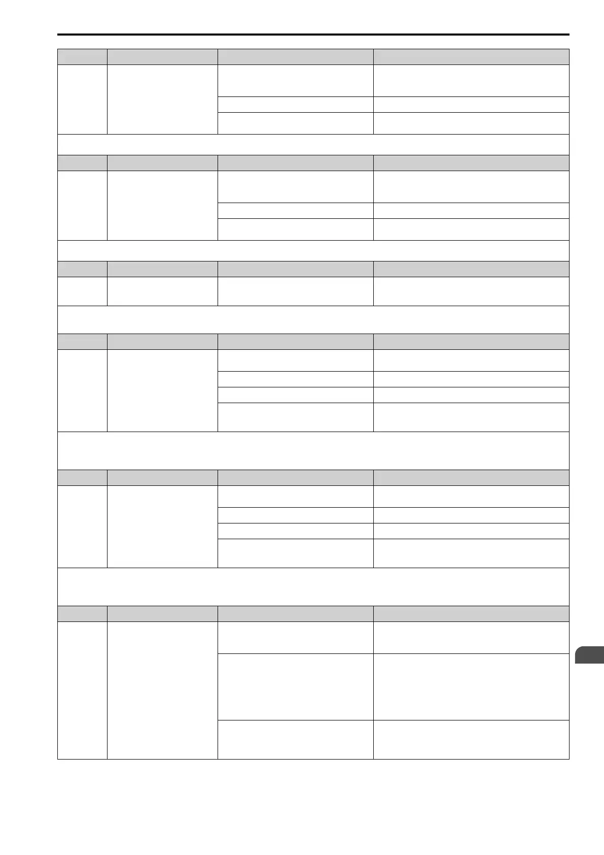
Code Name Causes Possible Solutions
EF6 External Fault (Terminal S6)
MFDI terminal S6 caused an external fault through
an external device.
1. Find the device that caused the external fault and remove the
cause.
2. Clear the external fault input in the MFDI.
The wiring is incorrect. Correctly connect the signal line to MFDI terminal S6.
External Fault [H1-06 = 2C to 2F] is set to MFDI
terminal S6, but the terminal is not in use.
Correctly set the MFDI.
Note:
If the drive detects this error, the terminal assigned to H2-01 to H2-03 = 10 [MFDO Function Select = Alarm] will activate.
Code Name Causes Possible Solutions
EF7 External Fault (Terminal S7)
MFDI terminal S7 caused an external fault through
an external device.
1. Find the device that caused the external fault and remove the
cause.
2. Clear the external fault input in the MFDI.
The wiring is incorrect. Correctly connect the signal line to MFDI terminal S7.
External Fault [H1-07 = 2C to 2F] is set to MFDI
terminal S7, but the terminal is not in use.
Correctly set the MFDI.
Note:
If the drive detects this error, the terminal assigned to H2-01 to H2-03 = 10 [MFDO Function Select = Alarm] will activate.
Code Name Causes Possible Solutions
EP24v External Power 24V Supply
The voltage of the main circuit power supply
decreased, and the 24 V power supply is supplying
power to the drive.
• Examine the main circuit power supply.
• Turn ON the main circuit power supply to run the drive.
Note:
• Set o2-26 [Ext. Power 24V Supply Display] to enable or disable EP24v detection.
• The drive will not output an alarm signal for this alarm.
Code Name Causes Possible Solutions
FbH Excessive PID Feedback
The FbH detection level is set incorrectly. Adjust b5-36 [PID High Feedback Detection Lvl] and b5-37 [PID
High Feedback Detection Time].
There is a problem with the PID feedback wiring. Correct errors with the PID control wiring.
The feedback sensor is not operating correctly. Examine the sensors on the control device side.
A fault occurred in the feedback input circuit of the
drive.
Replace the board or the drive. For information about replacing
the control board, contact Yaskawa or your nearest sales
representative.
Note:
• The drive detects this error if the PID feedback input is more than the level set in b5-36 for longer than b5-37.
• If the drive detects this error, the terminal set to H2-01 to H2-03 = 10 [MFDO Function Selection = Alarm] will activate.
• If the drive detects this error, it will operate the motor as specified by the stopping method set in b5-12 [Feedback Loss Detection Select].
Code Name Causes Possible Solutions
FbL PID Feedback Loss
The FbL detection level is set incorrectly. Adjust b5-13 [PID Feedback Loss Detection Lvl] and b5-14 [PID
Feedback Loss Detection Time].
There is a problem with the PID feedback wiring. Correct errors with the PID control wiring.
The feedback sensor is not operating correctly. Examine the sensors on the control device side.
A fault occurred in the feedback input circuit of the
drive.
Replace the board or the drive. For information about replacing
the control board, contact Yaskawa or your nearest sales
representative.
Note:
• The drive detects this error if the PID feedback input is lower than the level set in b5-13 for longer than b5-14.
• If the drive detects this error, the terminal set to H2-01 to H2-03 = 10 [MFDO Function Selection = Alarm] will activate.
• If the drive detects this error, it will operate the motor as specified by the stopping method set in b5-12 [Feedback Loss Detection Select].
Code Name Causes Possible Solutions
HCA High Current Alarm
The load is too heavy. • Decrease the load for applications with repetitive starts and
stops.
• Replace the drive with a larger capacity model.
The acceleration time is too short. • Calculate the torque necessary during acceleration related to
the load inertia and the specified acceleration time.
• Increase the values set in C1-01, C1-03, C1-05, or C1-07
[Acceleration Times] until you get the necessary torque.
• Increase the values set in C2-01 to C2-04 [S-Curve
Characteristics] until you get the necessary torque.
• Replace the drive with a larger capacity model.
The drive is trying to operate a specialized motor or
a motor that is larger than the maximum applicable
motor output of the drive.
• Examine the motor nameplate, the motor, and the drive to
make sure that the drive rated current is larger than the motor
rated current.
• Replace the drive with a larger capacity model.
 Loading...


