12.8 H: Terminal Function Selection
666 YASKAWA SIEPC71061753C GA500 Technical Manual
Note:
Refer to L8-03: Overheat Pre-Alarm Selection on page 729 for more information.
■ 4E: Braking Transistor Fault (rr)
Setting Value Function Description
4E Braking Transistor Fault
(rr)
The terminal activates when the internal braking transistor overheats and the drive detects an rr [Dynamic Braking Transistor
Fault] fault.
■ 4F: Braking Resistor Overheat (rH)
Setting Value Function Description
4F Braking Resistor Overheat
(rH)
The terminal activates when the braking resistor overheats and the drive detects an rH [Braking Resistor Overheat] fault.
The braking resistor overheats when the deceleration time is short and there is too much motor regeneration
energy.
■ 61: Pole Position Detection Complete
Setting Value Function Description
61 Pole Position Detection
Complete
The terminal activates when drive receives a Run command and the drive detects the motor magnetic pole position of the PM
motor.
■ 62: Modbus Reg 1 Status Satisfied
Setting Value Function Description
62 Modbus Reg 1 Status
Satisfied
The terminal activates when the bit specified by H2-08 [Modbus Register 1 Bit Select] for the MEMOBUS register address set
with H2-07 [Modbus Register 1 Address Select] activates.
■ 63: Modbus Reg 2 Status Satisfied
Setting Value Function Description
63 Modbus Reg 2 Status
Satisfied
The terminal activates when the bit specified by H2-10 [Modbus Register 2 Bit Select] for the MEMOBUS register address set
with H2-09 [Modbus Register 2 Address Select] activates.
■ 66: Comparator1
Setting Value Function Description
66 Comparator1
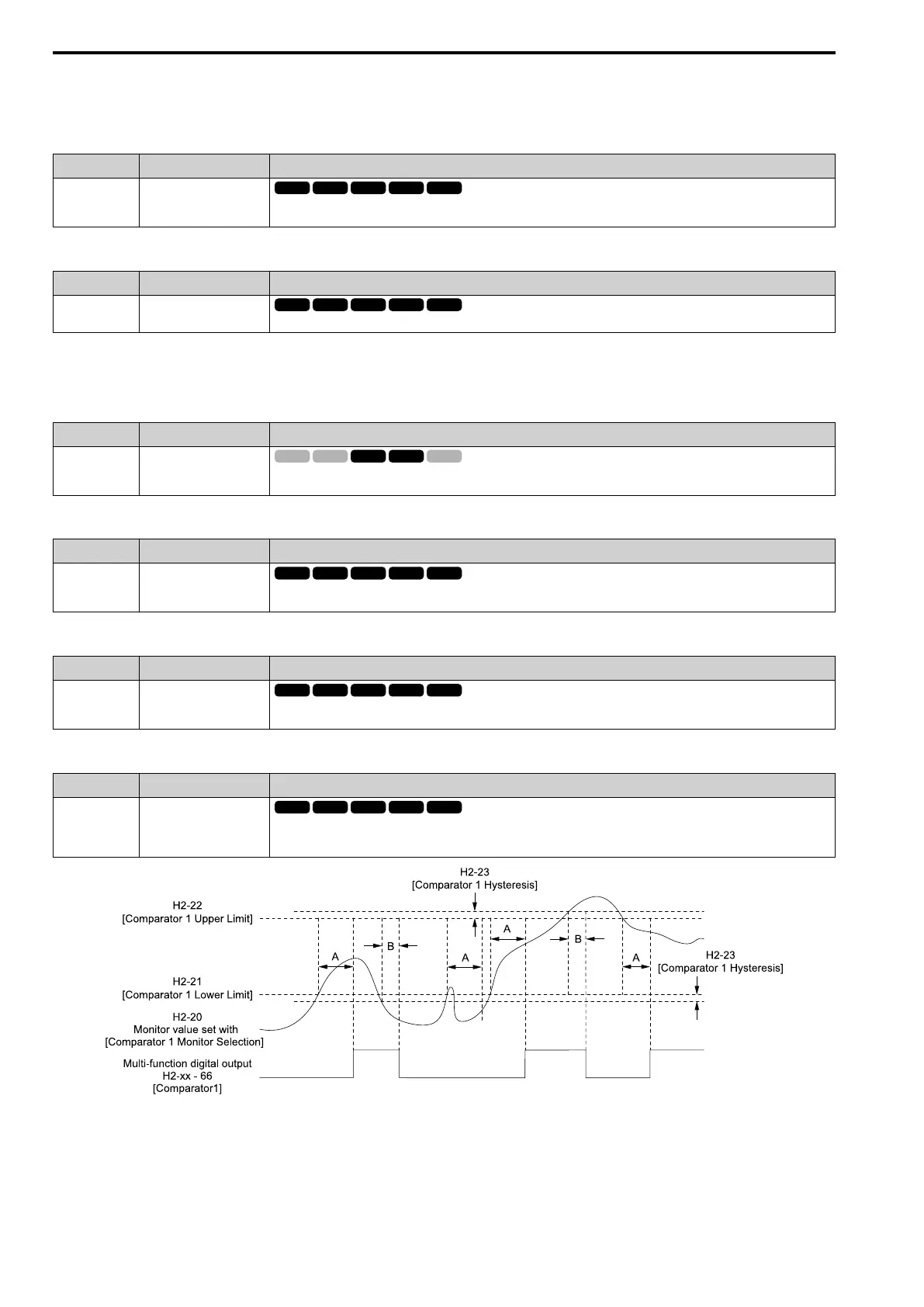
The terminal activates if the monitor value set with H2-20 [Comparator 1 Monitor Selection] is in range of the values of H2-21
[Comparator 1 Lower Limit] and H2-22 [Comparator 1 Upper Limit] for the time set in H2-24 [Comparator 1 On-Delay
Time].
A - H2-24
[Comparator 1 On-Delay Time]
B - H2-25
[Comparator 1 Off-Delay Time]
Figure 12.89 Comparator 1 Output Time Chart
Note:
The drive compares the monitors set with H2-20 as absolute values.
 Loading...


