n
C6-03/C6-04/C6-05: Carrier Frequency Upper Limit/Lower Limit/Proportional Gain
Use these parameters to set a user defined or a variable carrier frequency. To set the upper and lower limits, first set C6-02 to
“F”.
No. Parameter Name Setting Range Default
C6-03 Carrier Frequency Upper Limit 1.0 to 15.0 kHz 2.0 kHz
C6-04 Carrier Frequency Lower Limit 1.0 to 15.0 kHz 2.0 kHz
C6-05 Carrier Frequency Proportional Gain 0 to 99 0
Setting a Fixed User Defined Carrier Frequency
A carrier frequency between the fixed selectable values can be entered in parameter C6-03 when C6-02 is set to “F”. In V/f
Control, parameter C6-04 must also be adjusted to the same value as C6-03.
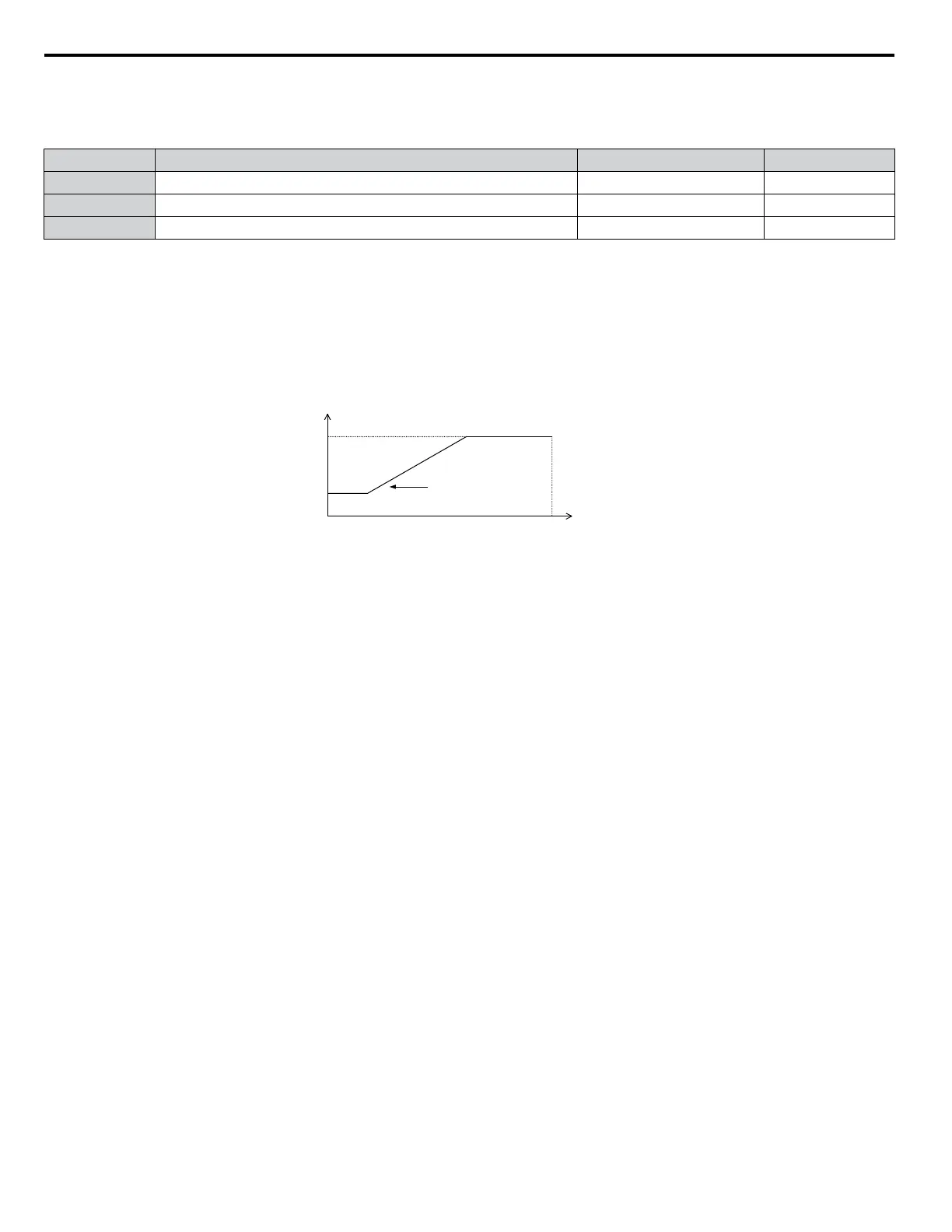
Setting a Variable Carrier Frequency
In V/f Control, the carrier frequency can be set up to change linearly with the output frequency. In this case the upper and
lower limits for the carrier frequency and the carrier frequency proportional gain (C6-03, C6-04, C6-05) have to be set as
shown in
Figure 5.29.
C6-03
C6-04
E1-04
x C6-05 x K*
Output Frequency
Output
Frequency
Max Output Frequency
Carrier Frequency
Figure 5.29 Carrier Frequency Changes Relative to Output Frequency
K is a coefficient determined by the value of C6-03:
• 10.0 kHz > C6-03 ≥ to 5.0 kHz: K = 2
• 5.0 kHz > C6-03: K = 1
• C6-03 ≥ 10.0 kHz: K = 3
Note: 1. A carrier frequency error (oPE11) will occur when the carrier frequency proportional gain is greater than 6 while C6-03 is less than
C6-04.
2. When C6-05 is set lower than 7, C6-04 is disabled and the carrier frequency will be fixed to the value set in C6-03.
5.3 C: Tuning
146
YASKAWA TOEP YAIQPM 03B YASKAWA AC Drive - iQpump Micro User Manual

 Loading...


