• Decrease the lag fixed speed delay (P9-07)
• Increase the staging frequency level (P9-09)
• Increase the staging delay time (P9-11)
• Increase the de-staging delay time (P9-15)
• Increase the stabilization time (P9-16)
• Increase both the Add Freq Level and Add Dly Time
Table 4.12 Related Parameters for Duplex System with Fine Tuning Application Example
Description
Drive A
<1>
Drive B
<1>
Run Source: 1 (Terminals) b1-02 = 1 b1-02 = 1
Node Address H5-01 = 1 H5-01 = 2
Highest Node Address P9-25 = 2 P9-25 = 2
Pump Mode: 3 (Network) P1-01 = 3 P1-01 = 3
Feedback Source: 0 (Analog) P9-02 = 0 P9-02 = 0
Lag Fixed Speed P9-06 = 54.0 Hz P9-06 = 54.0 Hz
Setpoint U5-99 = 100 PSI U5-99 = 100 PSI
Start Level P1-04 = 140 PSI P1-04 = 140 PSI
High Feedback Quick De-Stage P9-18 = 89.3% P9-18 = 89.3%
Setpoint Modifier P9-17 = 5.0 PSI P9-17 = 5.0 PSI
Add Drive Frequency Level P9-09 = 59.0 Hz P9-09 = 59.0 Hz
Add Drive Delay P9-11 = 12.0 s P9-11 = 12.0 s
<1> All other multiplexing and alternation parameters are set to default settings.
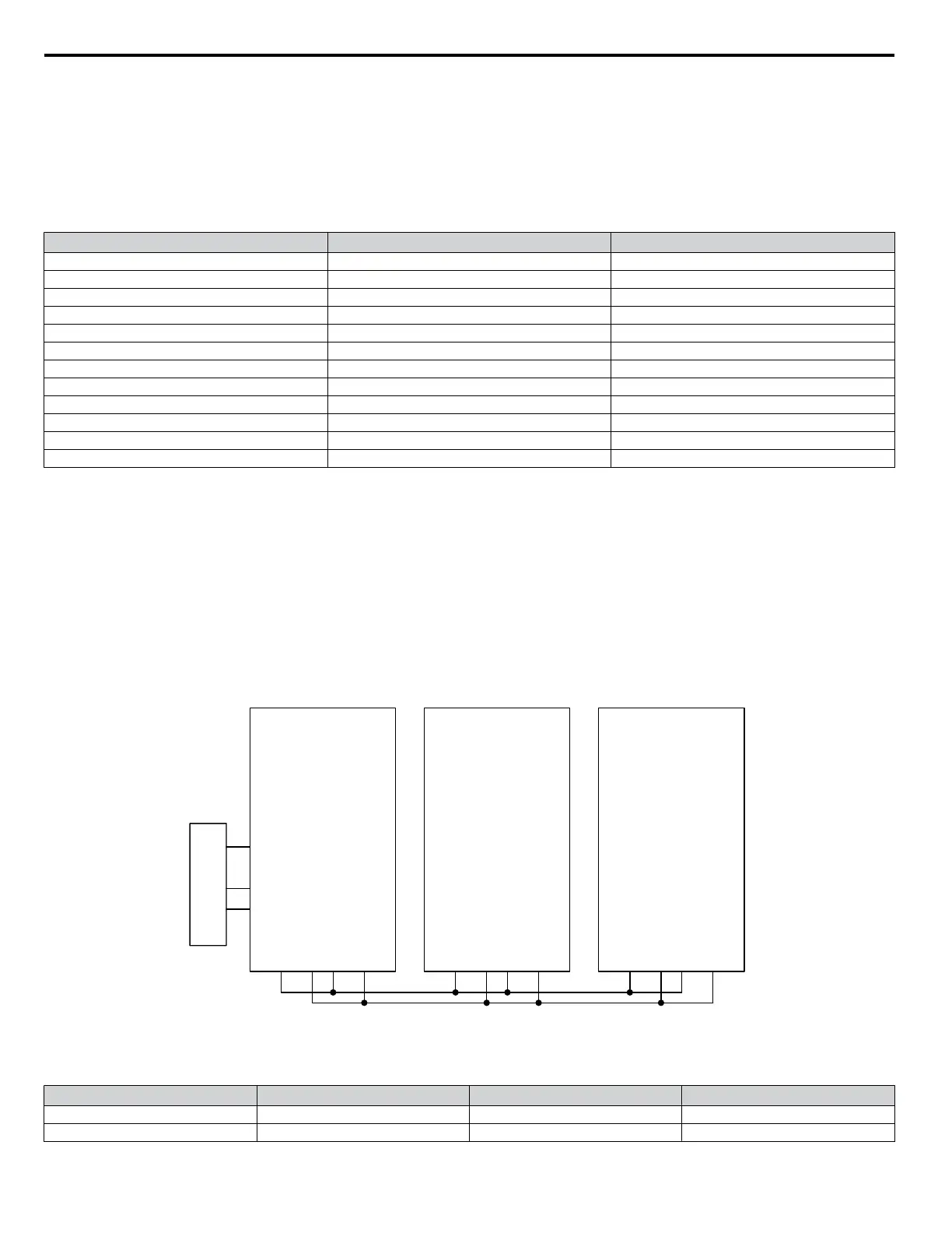
Duplex System with Jockey Pump Example
A customer requires a pump system with the following requirements:
• One small pump (the Jockey pump) will run the system during off-peak times.
• Two larger pumps will run the system when the demand is higher.
• The Jockey pump should not run when the two larger pumps are running.
• Pump wear is still an issue, but it is expected that the small pump will run longer hours and will always run first after a loss
of power.
• The feedback scale is 145 PSI.
• There is only one feedback transducer in the system.
(Jockey Pump)
10 HP
R+ S+ S-R-
A2
AC
+V
A1
SN
S1
Drive B
15 HP
R+ S+ S-R-
A2
AC
+V
A1
SN
S1
SYSTEM PRESSURE
FEEDBACK
Drive C
15 HP
R+ S+ S-R-
A2
AC
+V
A1
SN
S1
Figure 4.15 Simplified Wiring Diagram
Table 4.13 Related Parameters for Duplex System with Jockey Pump Example
Description
Jockey Pump
<1>
Drive B
<1>
Drive C
<1>
Node Address H5-01 = 1 H5-01 = 2 H5-01 = 3
Highest Node Address P9-25 = 3 P9-25 = 3 P9-25 = 3
4.8 iQpump Presets and Functions
98
YASKAWA TOEP YAIQPM 03B YASKAWA AC Drive - iQpump Micro User Manual

 Loading...


