9 Inspection, Maintenance, and Troubleshooting
9.1.4 Troubleshooting for Malfunction without Alarm Display
9-18
Abnormal
Noise from
servomotor
Mounting not secured
Check for any loose mounting screws. Tighten the mounting screws.
Check for misalignment of couplings. Align the couplings.
Check for unbalanced couplings. Balance the couplings.
Defective bearings
Check for noise and vibration around the
bearings.
If any abnormalities, contact your Yaskawa represen-
tative.
Vibration source on the driven
machine.
Any foreign matter, damages, or defor-
mation on the machine movable section.
Contact the machine manufacturer.
Noise interference due to incor-
rect input signal wire specifica-
tions.
The specifications of input signal wires
must be:
Tinned annealed copper twisted-pair or
twisted-pair shielded wires with core
0.12 mm
2
(0.0002 in
2
) min..
Use the specified input signal wires.
Noise interference due to long
length of input signal line
The maximum allowable cable length is
3 m (9.84 ft) and the impedance a few
hundreds ohm max.
Shorten the wiring distance for input signal line to
the specified range.
Noise interference due to incor-
rect encoder cable specifications.
The specifications of encoder cable must
be:
Tinned annealed copper twisted-pair or
twisted-pair shielded wires with core
0.12 mm
2
(0.0002 in
2
) min.
Use the specified encoder cable.
Noise interference due to long
encoder cable wiring
The maximum allowable cable length is
20 m (65.6 ft).
Shorten the encoder cable wiring distance to the
specified value.
Noise due to damaged encoder
cable
Check if the encoder cable is not dam-
aged or bent.
Modify the encoder cable layout.
Excessive noise to the encoder
cable
Check if the encoder cable is bundled
with high-current line or near the high-
current line.
Install a surge suppressor to the encoder cable.
FG varies by influence of
machines such as welder on the
servomotor side
Check if the machine is correctly
grounded.
Ground the machine separately from PG side FG.
SERVOPACK pulse counting
error due to noise
Check if there is noise interference on
the signal line from encoder.
Take measure against noise for the encoder wiring.
Excessive vibration and shock to
the encoder
Vibration from the machine or servomo-
tor incorrect installation
Reduce vibration from the machine, or secure the ser-
vomotor installation.
Encoder fault Encoder fault
Replace the motor.
Servomotor
Vibrates at
Approximate-
ly 200 to 400
Hz.
Speed loop gain value (Pn100) too
high.
Factory setting: Kv=40.0 Hz
Refer to the gain adjustment in User’s
Manual.
Reduce speed loop gain (Pn100) preset value.
Position loop gain value (Pn102)
too high
Factory setting: Kp=40.0/s
Refer to the gain adjustment in User’s
Manual.
Reduce position loop gain (Pn102) preset value.
Incorrect speed loop integral time
constant Pn101 setting
Factory setting: Ti=20.00 ms
Refer to the gain adjustment in User’s
Manual.
Correct the speed loop integral time constant Pn101
setting.
Incorrect moment of inertia ratio
data Pn103
Check the moment of inertia ratio data
Pn103.
Correct the moment of inertia ratio data Pn103.
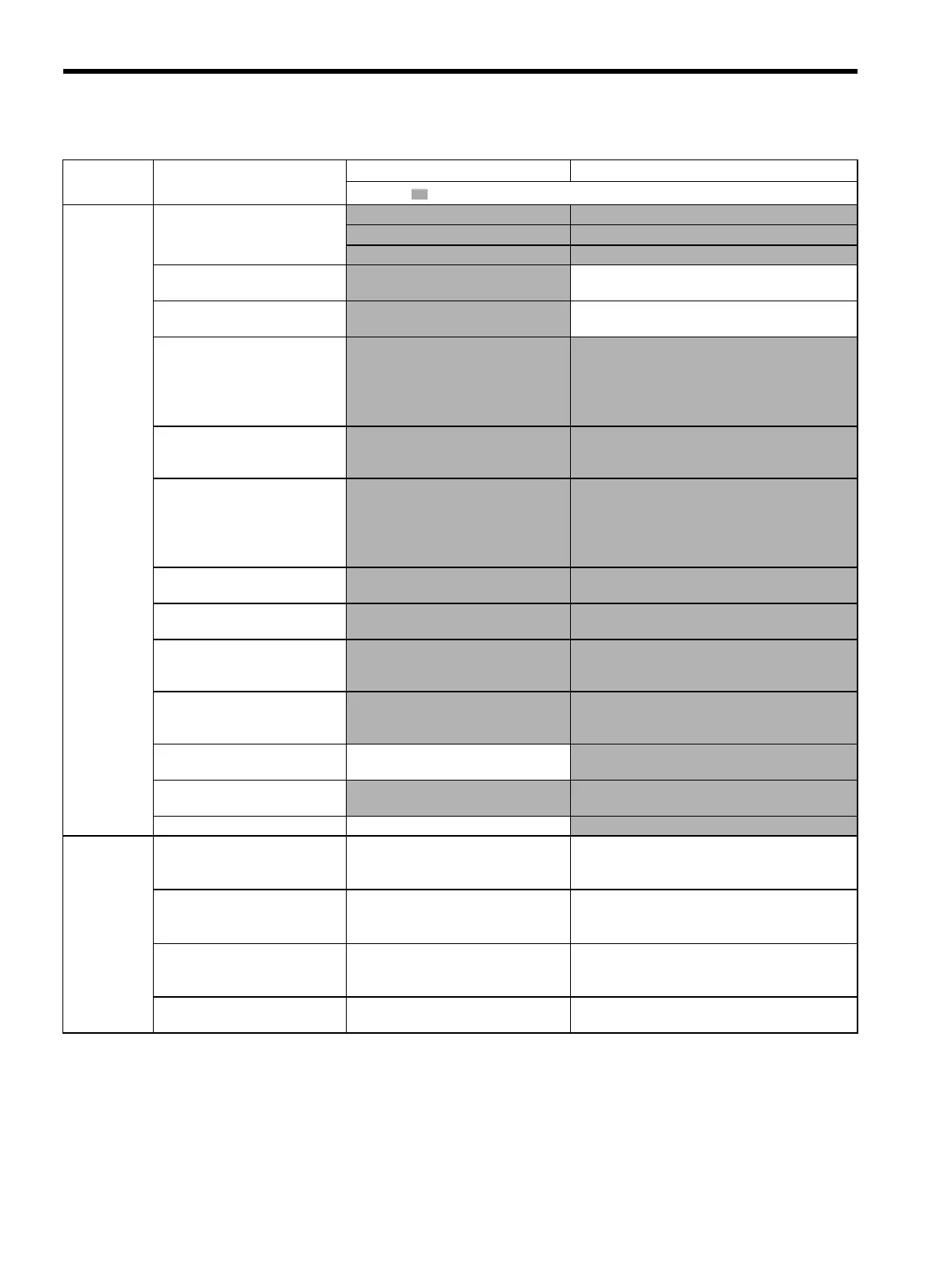
Table 9.5 Troubleshooting for Malfunction without Alarm Display (Cont’d)
Symptom Cause
Inspection Corrective Actions
: Turn OFF the servo system before executing operations.
SIEPS80000025.book 18 ページ 2004年10月25日 月曜日 午前11時57分