Wiring Main Circuit Terminals
2-17
Cable Length between Inverter and Motor
If the cable between the Inverter and the motor is long, the high-frequency leakage current will increase, caus-
ing the Inverter output current to increase as well. This may affect peripheral devices. To prevent this, adjust
the carrier frequency (set in C6-02) as shown in Table 2.7. (For details, refer to Chapter 5 User Constants.)
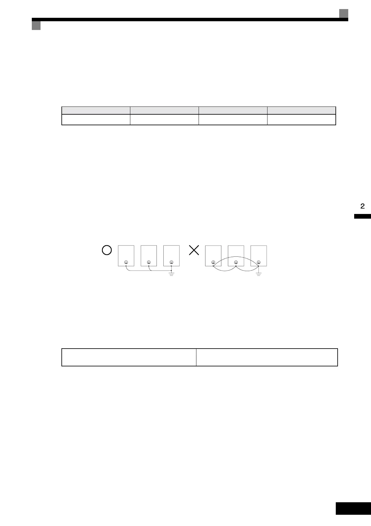
Ground Wiring
Observe the following precautions when wiring the ground line.
• Always use the ground terminal of the 200 V Inverter with a ground resistance of less than 100 Ω and that
of the 400 V Inverter with a ground resistance of less than 10 Ω.
• Do not share the ground wire with other devices, such as welding machines or power tools.
• Always use a ground wire that complies with technical standards on electrical equipment and minimize the
length of the ground wire.
Leakage current flows through the Inverter. Therefore, if the distance between the ground electrode and
the ground terminal is too long, potential on the ground terminal of the Inverter will become unstable.
• When using more than one Inverter, be careful not to loop the ground wire.
Fig 2.6 Ground Wiring
Connecting a Braking Unit (CDBR) and a Braking Resistor Unit (LKEB)
Connect a Braking Unit and a Braking Resistor Unit to the Inverter as shown in the Fig 2.7.
The Braking Resistor Unit will not work if L3-04 is set to 1 (i.e., if stall prevention is enabled for decelera-
tion). Hence the deceleration time may be longer than the set time (C1-02/04).
Table 2.7 Cable Length between Inverter and Motor
Cable length 50 m max. 100 m max. More than 100 m
Carrier frequency 15 kHz max. 10 kHz max. 5 kHz max.
Table 2.8
L3-04 (Stall prevention selection during deceleration)
(Select either of them.)
0 (Disable stall prevention function)
OK
NO
Artisan Technology Group - Quality Instrumentation ... Guaranteed | (888) 88-SOURCE | www.artisantg.com