4
-8
* This setting is for software versions PRG 1040 and later. The factory setting with software versions PRG 1039 and earlier depends on the Inverter capacity.
d1-01 to
d1-04 and
d1-17
Frequency ref-
erences 1 to 4
and jog fre-
quency refer-
ence
Set the required speed references for
multi-step speed operation or jogging.
0 to 400.00 Hz
d1-01 to
d1-04:
0.00 Hz
d1-17:
6.00 Hz
5-28
6-5
E1-01
Input voltage
setting
Set the Inverter's nominal input voltage in
volts.
This setting is used as a reference value in
protection functions.
155 to 255 V
(200 V Class)
310 to 510 V
(400 V Class)
200 V
(200 V
Class)
400 V
(400 V
Class)
5-34
6-122
E2-01
Motor rated
current
Set the motor rated current.
10% to 200%
of Inverter's
rated current
Setting for
general-
purpose
motor of
same
capacity
as Inverter
5-35
6-58
6-119
H4-02
and H4-
05
FM and AM
terminal out-
put gain
Set the voltage level gain for the multi-
function analog output 1 (H4-02) and 2
(H4-05).
Set the number of multiples of 10 V to be
output as the 100% output for the monitor
item.
0.00 to 2.50
H4-02:
1.00
H4-05:
0.50
5-55
L1-01
Motor protec-
tion selection
Set to enable or disable the motor overload
protection function using the electronic
thermal relay.
0: Disabled
1: General motor protection
2: Inverter motor protection
3: Vector motor protection
0 to 3 1
5-59
6-58
L3-04
Stall preven-
tion selection
during decel-
eration
0: Disabled (Deceleration as set. If
deceleration time is too short, a main
circuit overvoltage may result.)
1: Enabled (Deceleration is stopped when
the main circuit voltage exceeds the
overvoltage level. Deceleration restarts
when voltage is returned.)
2: Intelligent deceleration mode
(Deceleration rate is automatically
adjusted so that the Inverter can
d
ecelerate in the shortest possible time.
Set deceleration time is disregarded.)
3: Enabled (with Braking Resistor Unit)
When a braking option (Braking Resistor,
Braking Resistor Unit, Braking Unit) is
used, always set to 0 or 3.
0 to 3 1
5-62
6-25
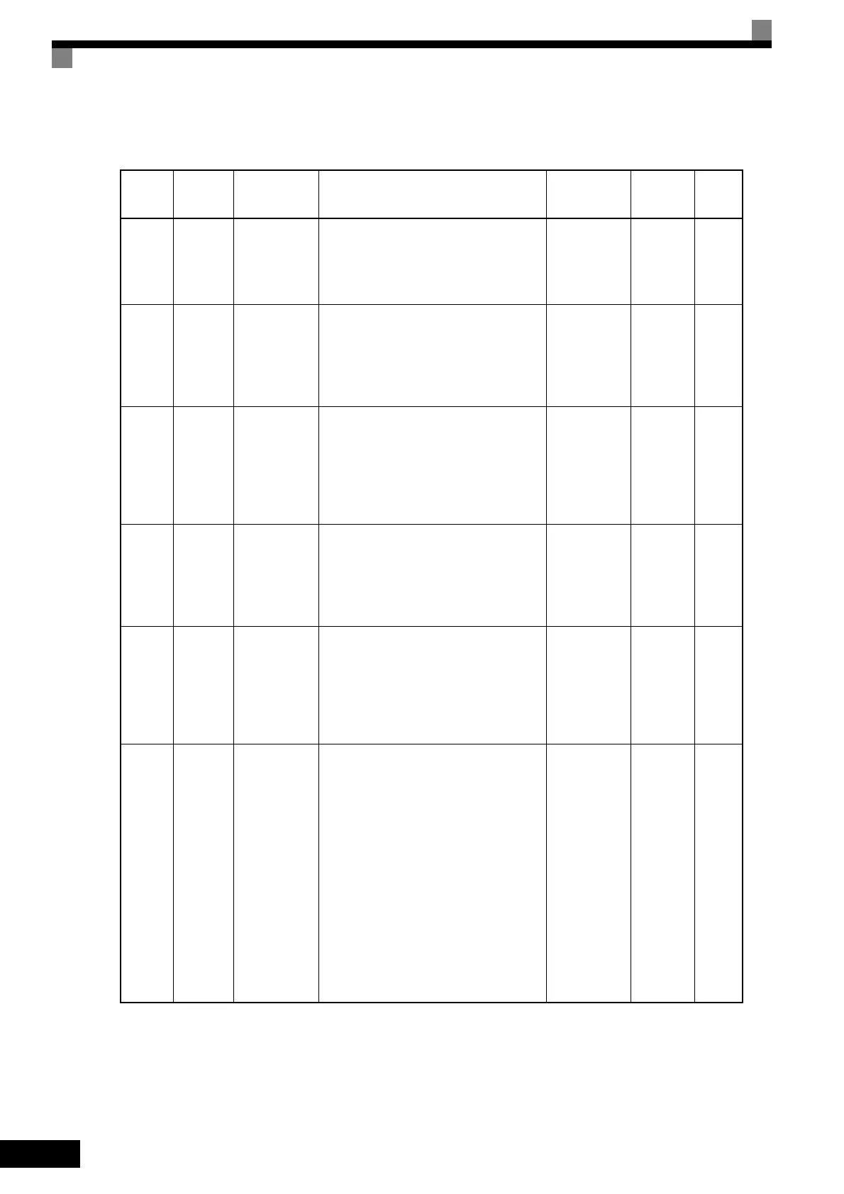
Table 4.1 Basic User Constant Settings (Continued)
: User constants that must be set, : User constants to be set as necessary.
Cate-
gory
Con-
stant
Number
Name Description
Setting
Range
Factory
Setting
Page
TOE-S616-60.1.book 8 ページ 2017年8月4日 金曜日 午後3時41分

 Loading...


