4
-32
* 1. The setting is given for 200 V Class Inverters. Double the voltage for 400 V Class Inverters.
* 2. The adjustment procedure is described in the following section.
* 3. This refers to the frequency near the N4-11 set value when accelerating and the N4-28 set value when decelerating.
* 4. This means that the ratios of E1-10 to E1-09 and E1-08 to E1-07 are close to the ratio of E1-13 to E1-06. If the V/f pattern is too close to a straight line,
the power will be reduced. Do not change the setting more than necessary.
* 5. Adjust the following user constants only when problems occur: b1-10, d5-07, N4-11, N4-28, N4-15, N4-17, N4-29, N4-30, and N4-32 to N4-34.
* 6. This setting is for software versions PRG 1040 and later. The factory setting with software versions PRG 1039 and earlier depends on the Inverter
capacity.
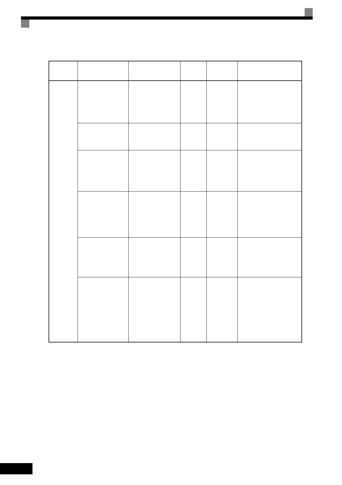
Open-loop
vector 2
control
(A1-02 = 4)
(Continued)
N4-11 (Speed
estimator switching
frequency)
*5
N4-28 (Speed
estimator switching
frequency 2)
*5
Countermeasure when
shock is a problem
near the speed estima-
tor switching fre-
quency
*3
N4-11:
70 Hz
N4-28:
50 Hz
Lower than
default value
Reduce the values of N4-11
and N4-28. (Typically, 5 Hz.)
If the problem is not
improved, use open-loop
vector 1 control (A1-02=2).
N4-15 (Low-speed
regeneration stability
coefficient 1)
*5
Load tolerance (low-
speed regenerative
loads)
0.3
Default
value
Increase the setting if the
power in low-speed regener-
ation is low. (Typically,
increase in intervals of 0.1.)
N4-17 (Torque
adjustment gain)
*5
The torque reference
value (U1-09) in the
low-speed range is
large compared with
the medium- and high-
speed ranges.
0.8 0.8 to 1.0
Increase the setting to 1.0
max. (Typically, increase in
intervals of 0.05.) If the prob-
lem is not improved, bring
the V/f pattern close to a
straight line.
*4
N4-29 (Torque
adjustment gain 2)
*5
Load tolerance (low-
speed electrical loads)
0.10
Default
value
Increase the setting if the
power in low-speed electrical
operation is low. (Typically,
increase in intervals of 0.05.)
Increasing the setting too
much will have the opposite
effect.
N4-30 (Low-speed
regeneration stability
coefficient 2)
*5
Controlling hunting
and vibration (low-
speed regenerative
loads)
1.0 1.0 to 2.5
If vibration occurs during
low-speed regeneration,
increase the setting until the
speed increase becomes a
problem. (Typically, increase
in intervals of 0.2.)
N4-32 to N4-34
(Speed estimator gain
fluctuation frequency
1, 2, and fluctuation
rate)
*5
Controlling hunting
and vibration (6 to 10
Hz)
N4-32:
5 Hz
N4-33:
20 Hz
N4-34:
100%
N4-32:
Around 5 Hz
N4-33:
20 Hz or less
N4-34: 50%
to 100%
First accelerate the motor
gradually and set N4-32 to
the lowest speed at which
vibration occurs. Set N4-33
to the highest speed at which
vibration occurs. And then
reduce the setting of N4-34
until the vibration stops.
(Typically, change in inter-
vals of 5%.)
Table 4.3 Adjusted User Constants (Continued)
Control
Method
Name (Constant
Number)
Performance
Factory
Setting
Recom-
mended
Setting
Adjustment Method
TOE-S616-60.1.book 32 ページ 2017年8月4日 金曜日 午後3時41分

 Loading...


