User Constant Tables
5-
83
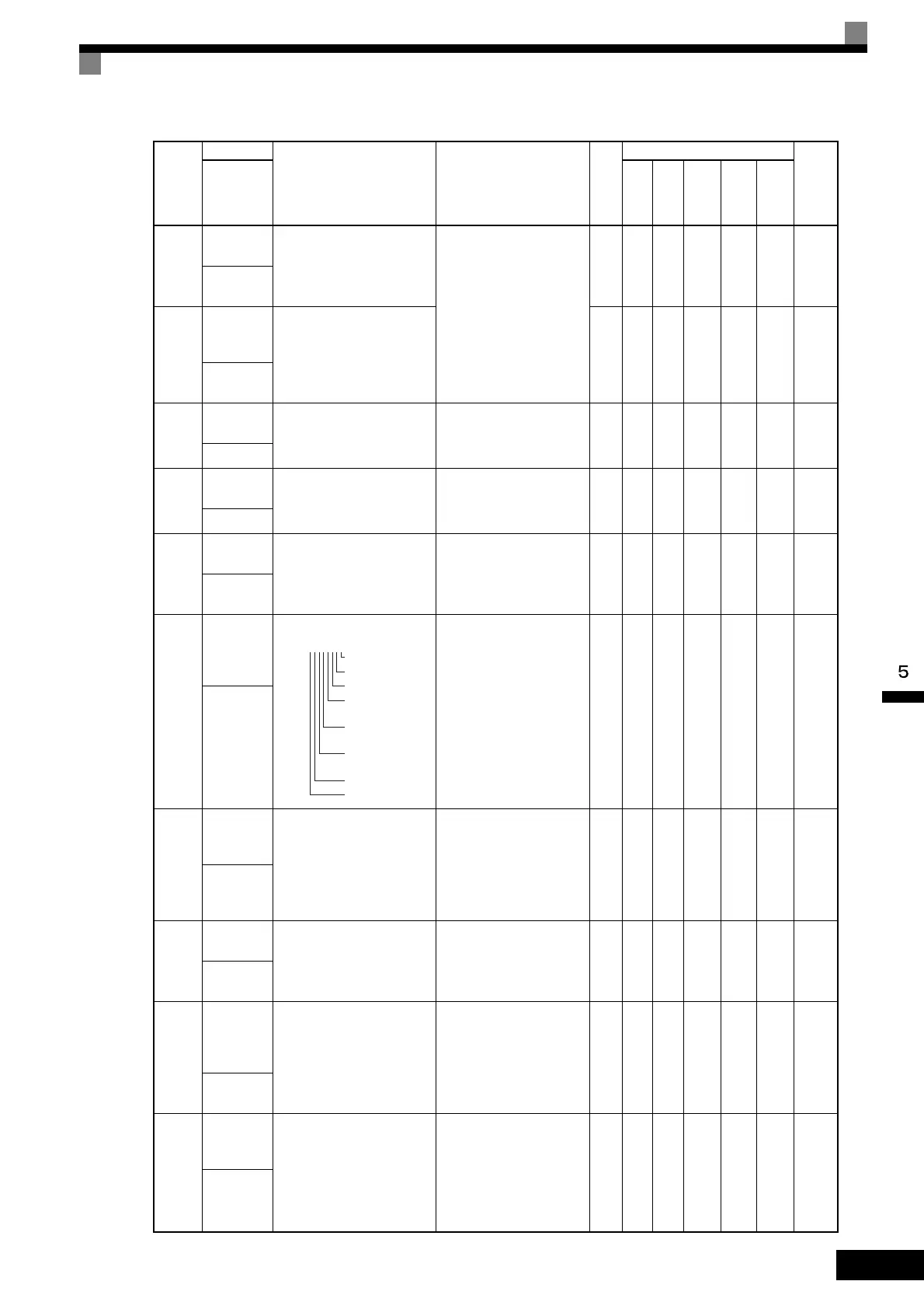
U1-34
OPE fault
constant
Shows the first constant num-
ber where an OPE fault was
detected.
(Cannot be output.)
– A A A A A 61H
OPE
Detected
U1-35
Zero-servo
movement
pulses
Shows the number of PG
pulses times 4 for the move-
ment range when stopped at
zero.
1 No No No A No 62H
Zero Servo
Pulse
U1-36
PID input
volume
PID feedback volume
Given as maximum frequency/
100%
10 V: Max. frequency
(-10 to 10 V possible)
0.01
%
A A A A A 63H
PID Input
U1-37
PID output
volume
PID control output
Given as maximum frequency/
100%
10 V: Max. frequency
(-10 to 10 V possible)
0.01
%
A A A A A 64H
PID Output
U1-38
PID target
value
PID target value
Given as maximum frequency/
100%
10 V: Max. frequency
0.01
%
A A A A A 65H
PID Set-
point
U1-39
MEMOBUS
communi-
cations
error code
Shows MEMOBUS errors.
(Cannot be output.) – A A A A A 66H
Transmit
Err
U1-40
Cooling fan
operating
time
Monitors the total operating
time of the cooling fan. The
time can be set in 02-10.
(Cannot be output.)
1
hr
A A A A A 68H
FAN
Elapsed
Time
U1-42
Estimated
motor flux
Monitors the calculated value
of the motor flux. 100% is dis-
played for the rated motor
flux.
10 V: Rated motor flux
0.1
%
No No No No A 69H
Mot Flux
EST
U1-43
Motor flux
current
compensa-
tion
Monitors motor flux current
compensation value. 100% is
displayed for the rated second-
ary current of the motor.
10 V: Rated secondary cur-
rent of motor
(-10 V to 10 V)
0.1
%
No No No No A 6AH
Id Comp
Va lu e
U1-44
ASR out-
put without
filter
Monitors the output from the
speed control loop (i.e., the
primary filter input value).
100% is displayed for rated
secondary current of the
motor.
10 V: Rated secondary cur-
rent of motor
(-10 V to 10 V)
0.01
%
No No No A A 6BH
ASR Out-
put w Fil
Con-
stant
Number
Name
Description
Output Signal Level
During Multi-Function
Analog Output
Min.
Unit
Control Methods
MEMO-
BUS
Regis-
ter
Display
V/f
V/f
with
PG
Open
Loop
Vec-
tor
1
Flux
Vec-
tor
Open
Loop
Vec-
tor
2
1: CRC error
1: Data length error
Not used (always 0).
1: Parity
error
1: Overrun
error
1: Framing
error
1:
Timeout
Not used (always 0).
U1-39= 00000000
TOE-S616-60.1.book 83 ページ 2017年8月4日 金曜日 午後3時41分

 Loading...


