5
-86
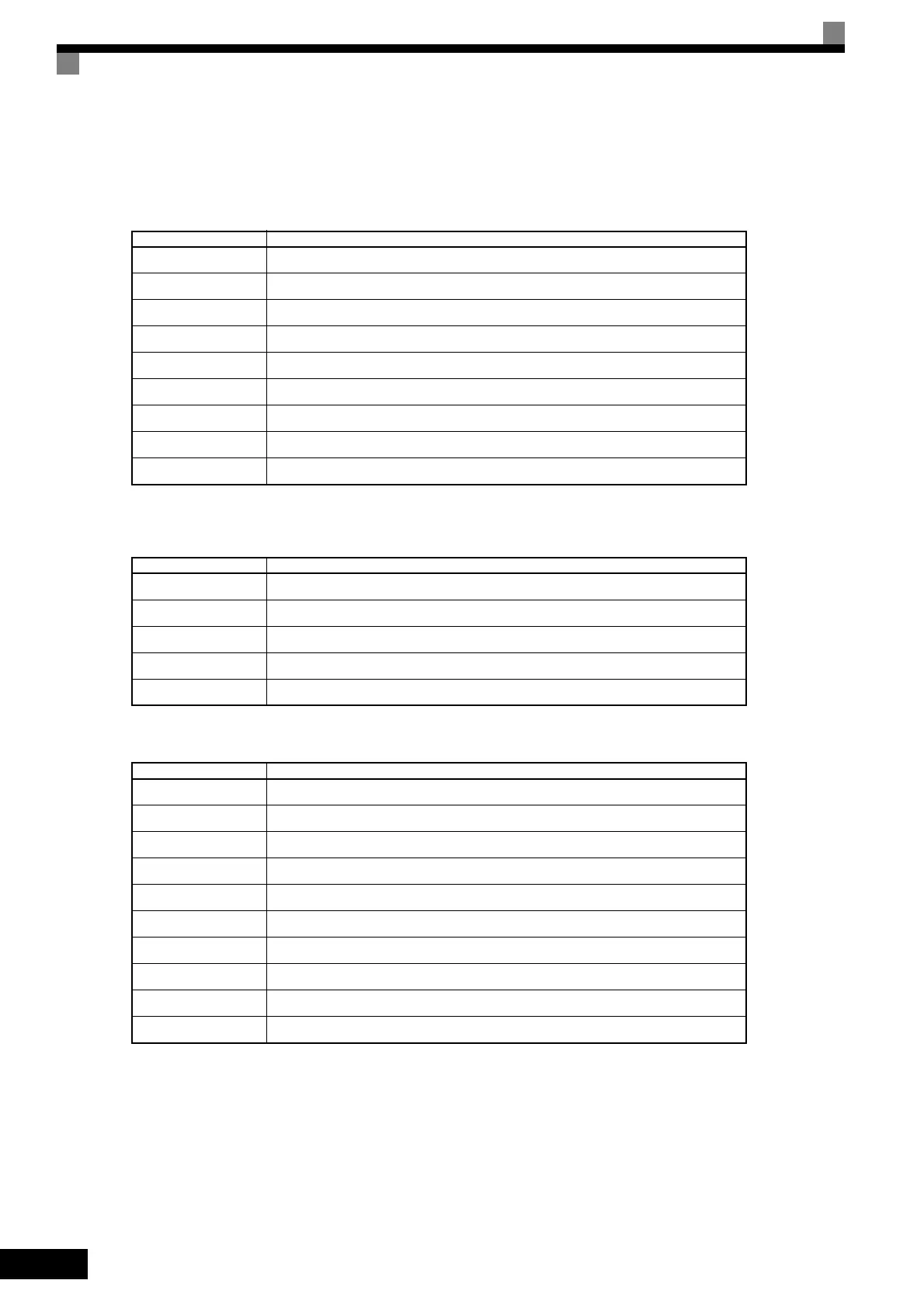
Details on U1-85 and U1-86 Settings
U1-85 = Y-nn
U1-86 = Y-nn
Table 5.1 Frequency Reference Source
Y-nn Description
0-01
LED/LCD Digital Operator
1-01
Analog input terminal (A1 terminal)
1-02
Analog input terminal (A2 terminal)
1-03
Analog input terminal (A3 terminal)
2-02 to 2-17
Multi-step speed reference (d1-02 to d1-17)
3-01
MEMOBUS communications
4-01
Option board
5-01
Pulse reference input
6-01
CASE
Table 5.2 Run Command Source
Y Description
0
LED/LCD Digital Operator
1
Control circuit terminal (sequence input)
3
MEMOBUS communications
4
Option board
6
CASE
Table 5.3 Run Command Restrictions
nn Description
00
Not restricted.
01
Run Command turned ON while stopped in a programming mode.
02
Run Command turned ON after switching from LOCAL to REMOTE.
03
Waiting for MCON after the power supply was turned ON (UV1 or UV will flash after 10 seconds).
04
Restarting is prohibited after stopping.
05
Emergency stop (multi-function contact input or Digital Operator (LED/LCD))
06
Not used
07
Restarting is prohibited after coasting to stop with timer.
08
Baseblock because frequency reference is less than E1-09 (Minimum Output Frequency).
09
Waiting for ENTER command.
TOE-S616-60.1.book 86 ページ 2017年8月4日 金曜日 午後3時41分

 Loading...


