6
-6
Setting Precautions
Refer to the following to set step 1 to step 3 to analog inputs.
• Step 1
When setting terminal A1's analog input to step 1, set b1-01 to 1, and when setting d1-01 (Frequency Ref-
erence 1) to step 1, set b1-01 to 0.
• Step 2
When setting terminal A3's analog input to step 2, set H3-05 to 2 (auxiliary frequency reference 1). When
setting d1-02 (Frequency Reference 2) to step 2, set H3-05 to 1F (Analog input not used).
• Step 3
When setting terminal A2's analog input to step 3, set H3-09 to 3 (auxiliary frequency reference 2). When
setting d1-03(Frequency Reference 3) to step 3, set H3-05 to 1F (Analog input not used).
When inputting 0 to 10 V to terminal A2’s analog input, set H3-08 to 0, and turn OFF DIP switch pin S1-2
on the control circuit terminal board. (Refer to page 2-33.)
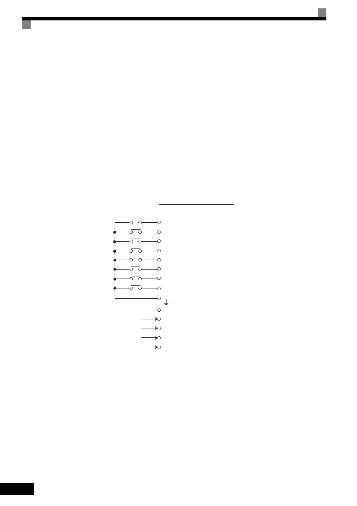
Connection Example and Time Chart
The following diagram shows a time chart and control circuit terminal connection example during a 9-step
operation.
Fig 6.6 Control Circuit Terminal During 9-step Operation
Inverter
Forward/stop
Reverse/stop
External fault
Fault reset
Multi-step speed reference 1
Multi-step speed reference 2
Multi-step speed reference 3
Jog frequency
SC Sequence common
Frequency setting power (+15 V)
Master speed referennce (0 to 10 V)
[Master speed frequency (b1-01 = 1)]
Master speed referennce (4 to 20 mA)
[Auxiliary speed frequency1 (H3-09 = 2)]
Auxiliary speed frequency (0 to 10 V)
[Auxiliary speed frequency 2 (H3-05 = 3)]
Analog common 0 V
S1
S2
S3
S4
S5
S6
S9
S7
+V
A1
A2
A3
AC
TOE-S616-60.1.book 6 ページ 2017年8月4日 金曜日 午後3時41分

 Loading...


