6
-30
Adjusting Frequency Gain Using an Analog Input
When H3-09 or H3-05 is set to 1 (frequency gain), you can adjust the frequency gain using the analog input
terminal A2 or A3.
Fig 6.27 Frequency Gain Adjustment (Terminal A2 Input)
The frequency gain for terminal A1 is the product of H3-02 and terminal A2 gain. For example, when H3-02
is set to 100% and terminal A2 is set to 5 V, the terminal A1 frequency reference will be 50%.
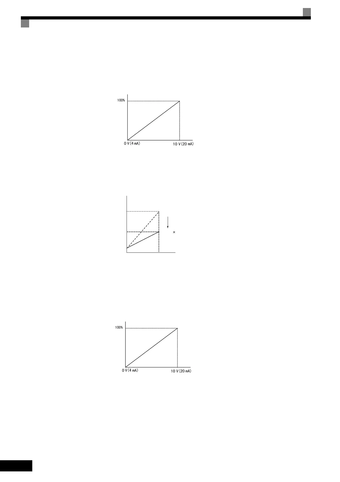
Adjusting Frequency Bias Using an Analog Input
When constant H3-09 or H3-05 is set to 0 (add to terminal A1), the frequency equivalent to the terminal A2 or
A3 input voltage is added to A1 as a bias.
Fig 6.28 Frequency Bias Adjustment (Terminal A2 or A3 Input)
For example, if H3-02 is 100%, H3-03 is 0%, and terminal A2 is set to 1 V, the frequency reference from
terminal A1 when 0 V is input to A1 will be 10%.
Frequency gain
Multi-function analog input
terminal A2 input level
Frequency reference
H3-02
H3-02
0.5
0 10 V
Terminal A1 input voltage
100%
50%
Frequency bias
Multi-function analog input
terminal A2 or A3 input level
TOE-S616-60.1.book 30 ページ 2017年8月4日 金曜日 午後3時41分

 Loading...


