Machine Protection
6-
45
Fig 6.35
•
With vector control, the carrier frequency is fixed to the Carrier Frequency Upper Limit in C6-03 if user-
set or by the carrier frequency set in C6-02.
• To fix the carrier frequency, set C6-03 and C6-04 to the same value, or set C6-05 to 0.
• If the settings are as shown below, OPE11 (Constant setting error) will occur.
If Carrier Frequency Proportional Gain (C6-05) > 6 and C6-03 < C6-04.
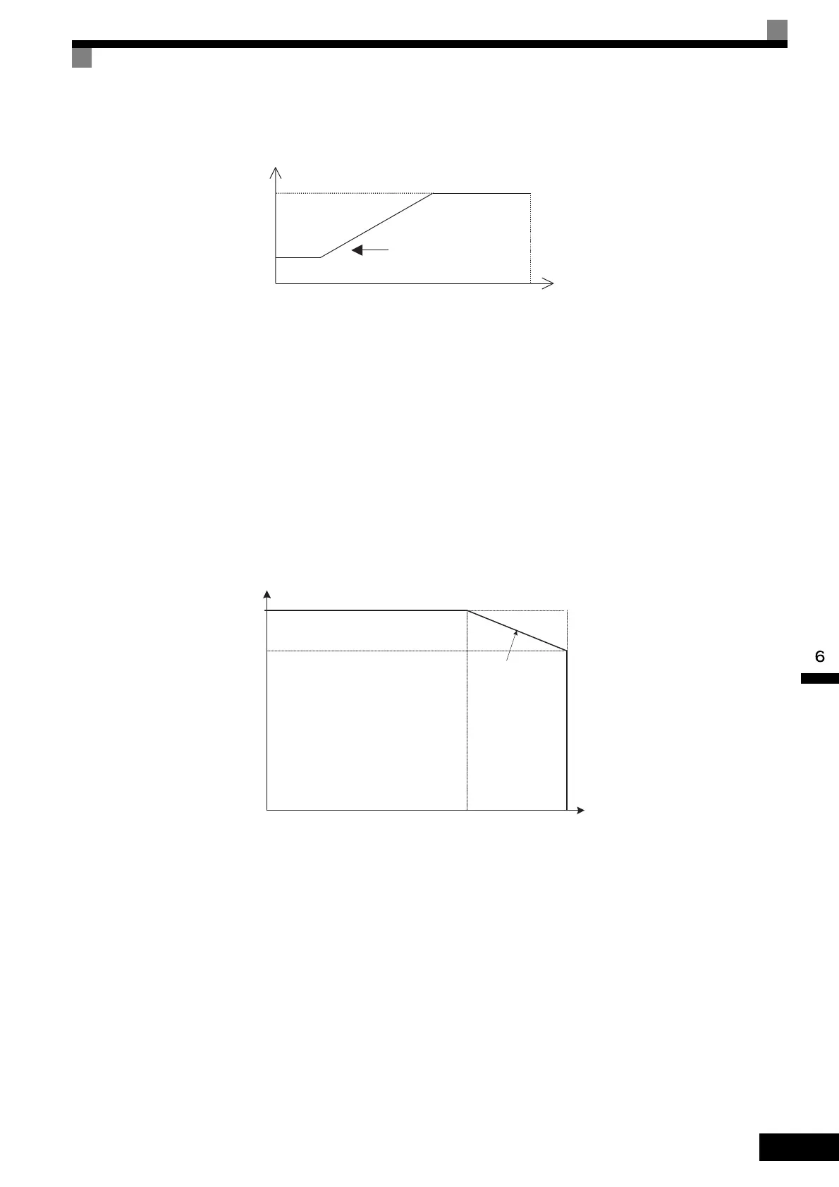
• The Inverter overload current level can be reduced by the carrier frequency setting, and an OL2 (Inverter
overload) may be detected even if the overload current is smaller than 150%. The reduction levels of the
Inverter overload current are shown in the following figures.
Fig 6.36 Reduction Levels for V/f, V/f with PG, Open-loop Vector 1, and Flux Vector Control
Output frequency
Output frequency ´ C6-05
´ K*
E1-04
Max. Output Frequency
Carrier Frequency
K is the coefficient determined by the set
value in C6-03.
C6-03 ³ 10.0 kHz: K = 3
10.0 kHz > C6-03 ³ 5.0 kHz: K = 2
5.0 kHz < C6-03: K = 1
*
100%
15 kHz0
Overload current reduction level
Carrier frequency
50%
80%
200 V Class,
22 kW
10 kHz
TOE-S616-60.1.book 45 ページ 2017年8月4日 金曜日 午後3時41分

 Loading...


