6
-46
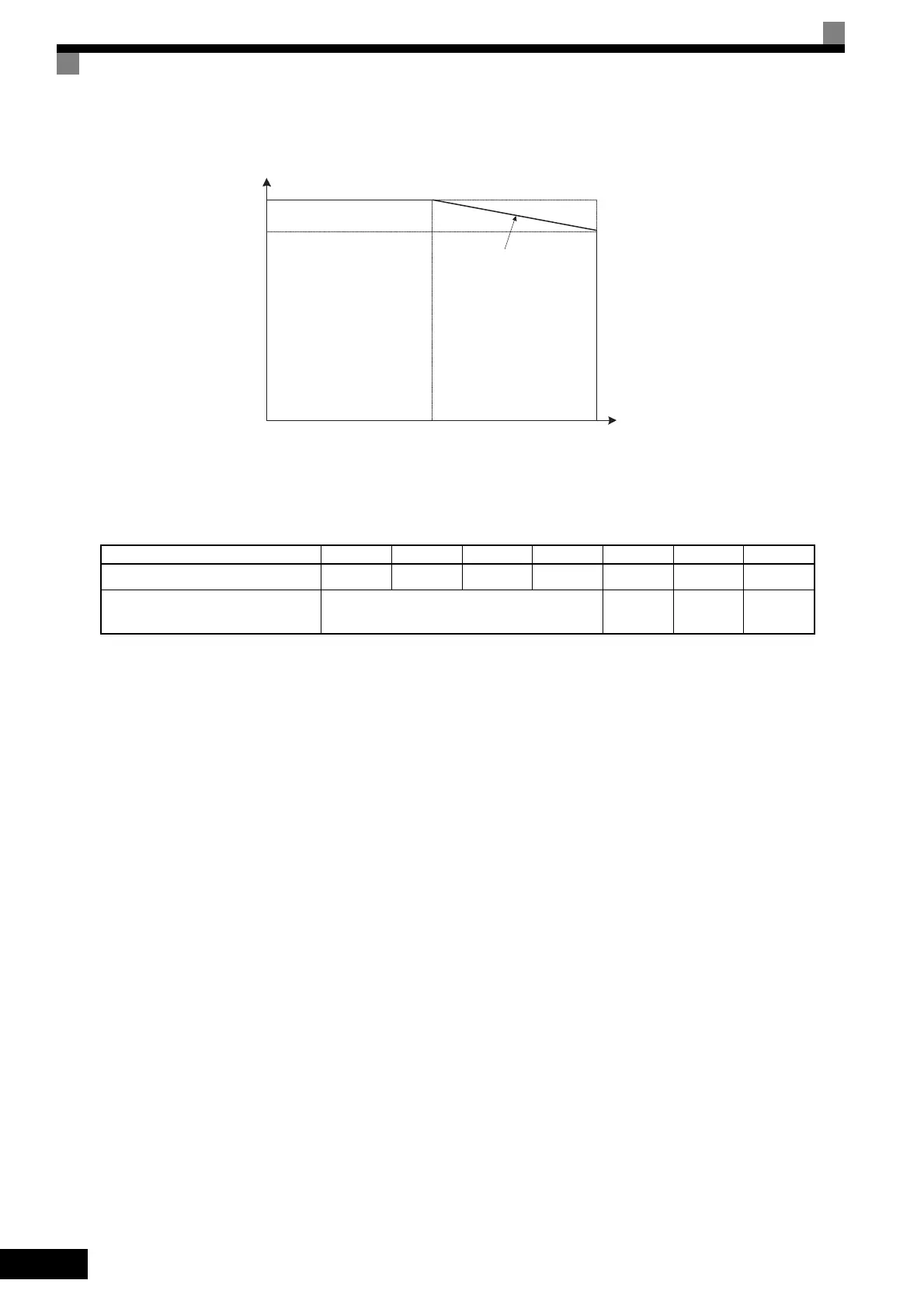
Fig 6.37 Reduction Levels for Open-loop Vector 2 Control
For 400 V Class Inverters, the following limitations apply to the maximum output frequency that can be set
for the carrier frequency settings.
Motor 2 Carrier Frequency Setting Precautions
Observe the following precautions when using motor 2 with a 400 V Class Inverter with a capacity of 90 kW
to 220 kW.
• C6-02 (Carrier Frequency Selection), C6-03 (Carrier Frequency Upper Limit), and C6-04 (Carrier Fre-
quency Lower Limit) cannot be set while motor 2 is selected.
• Except in the following case, the carrier frequency of motor 2 is the same as motor 1.
When the setting of C6-03 (Carrier Frequency Upper Limit) is out of the setting range for E3-01 (Motor 2
Control Method Selection).
When switching to motor 2 in this case, the setting of C6-03 (Carrier Frequency Upper Limit) is set to the
upper limit of the setting range for E3-01 (Motor 2 Control Method Selection).
Carrier Frequency 0.4 kHz 1 kHz 1.5 kHz 2 kHz 3 kHz 5 kHz 8 kHz
Maximum output frequency setting 33 Hz 83 Hz 125 Hz 166 Hz 250 Hz 400 Hz 400 Hz
Applicable Inverter capacity
CIMR-G7
40P4 to 4300
40P4 to
4110
40P4 to
4075
40P4 to
4045
100%
8 kHz0
50%
87%
4 kHz
Overload current reduction level
Carrier frequency
200 V Class,
30 to 75 kW
TOE-S616-60.1.book 46 ページ 2017年8月4日 金曜日 午後3時41分

 Loading...


