6
-62
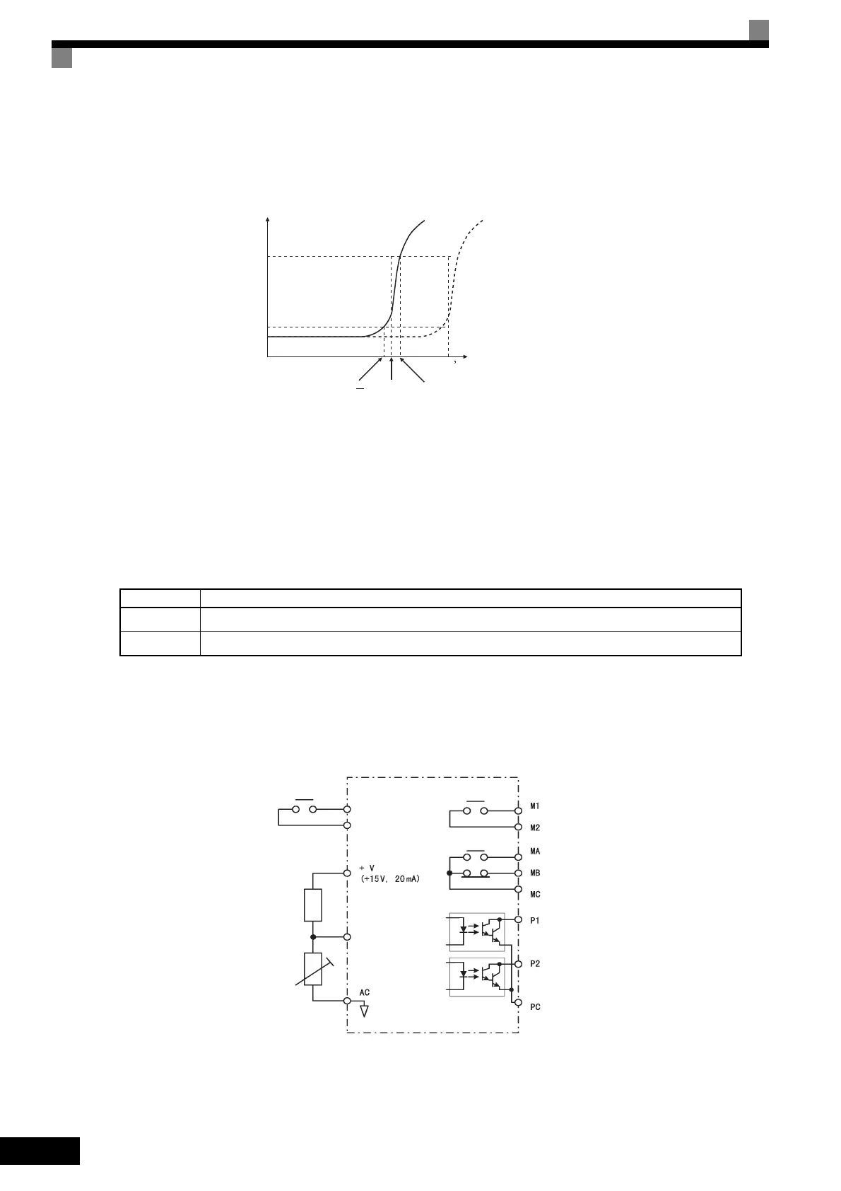
PTC Thermistor Characteristics
The following diagram shows the characteristics of the PTC thermistor temperature to the resistance value.
Fig 6.43 PTC Thermistor Temperature-Resistance Value Characteristics
Operation during Motor Overheating
Set the operation if the motor overheats in constants L1-03 and L1-04. Set the motor temperature input filter
time constant in L1-05. If the motor overheats, the OH3 and OH4 error codes will be displayed on the Digital
Operator.
Error Codes If the Motor Overheats
By setting H3-09 (Multi-function Analog Input Terminal A2 Function Selection) or H3-05 (Multi-function
Analog Input Terminal A3 Function Selection) to E (Motor temperature input), you can detect alarm OH3 or
OH4 using the PTC temperature-resistance characteristics, and protect the motor. The terminal connections
are shown in the following diagram. Set H3-08[Signal level selection (terminal A2)](H3-04 when A3 is used)
to 0 (0 to + 10 V).
Fig 6.44 Mutual Connections During Motor Overheating Protection
Error Code Details
OH3 Inverter stops or continues to operate, according to the setting in L1-03.
OH4 Inverter stops according to the setting in L1-04.
Tr: Temperature threshold value
Tr
Tr+5TrTr 5
550
1330
Resistance (ohms)
Class F
150°C
Class H
180°C
Temperature
A2, A3
(0-10 V)
* When using terminal A2, set DIP switch S1-2 to OFF (0 to 10 V).
Inverter
Multi-function
contact input
Branch resistance
18 kΩ
PTC thermistor
Multi-function
contact output
Fault contact
output
Multi-function
PHC output
TOE-S616-60.1.book 62 ページ 2017年8月4日 金曜日 午後3時41分

 Loading...


