Input Terminal Functions
6-
81
Application Precautions
• Frequency outputs using UP/DOWN commands are limited by the frequency reference upper and lower
limits set in constants d2-01 to d2-03. Here, frequency references from analog frequency reference termi-
nal A1 becomes the frequency reference lower limit. If using a combination of the frequency reference
from terminal A1 and the frequency reference lower limit set in either constant d2-02 or d2-03, the larger
lower limit will become the frequency reference lower limit.
• If the UP and DOWN commands and multi-step speed reference have been assigned at the same time, the
multi-step speed references are disabled.
• When d4-01 (Frequency Reference Hold Function Selection) is set to 1, the frequency reference held using
the UP/DOWN functions is stored even after the power supply is turned OFF. When the power supply is
turned ON and the Run Command is input, the motor accelerates to the frequency reference that has been
stored. To reset (i.e., to 0 Hz) the stored frequency reference, turn ON the UP or DOWN command while
the Run Command is OFF.
• If the lower limit of the frequency reference is set only with d2-02, the Inverter accelerates to the lower
limit of the frequency reference as soon as the Run Command is turned ON.
• If both the Inverter’s Run Command and UP and DOWN commands are valid when the lower limit of the
frequency reference is set only with the frequency reference from analog frequency reference terminal A1,
the Inverter will accelerate to the lower limit of the frequency reference that was set. If only the Run Com-
mand is valid, the Inverter will not start to accelerate.
• If the lower limit of the frequency reference from analog frequency reference terminal A1 is higher than
the setting of d2-02 when the lower limit of the frequency reference is set with both the frequency refer-
ence from analog frequency reference terminal A1 and the setting of d2-02, the Inverter will accelerate to
the setting of d2-02 when the Run Command is turned ON. If the UP and DOWN commands are valid
when the Inverter has accelerated to the setting of d2-02, the Inverter will accelerate to the lower limit of
the frequency reference from analog frequency reference terminal A1.
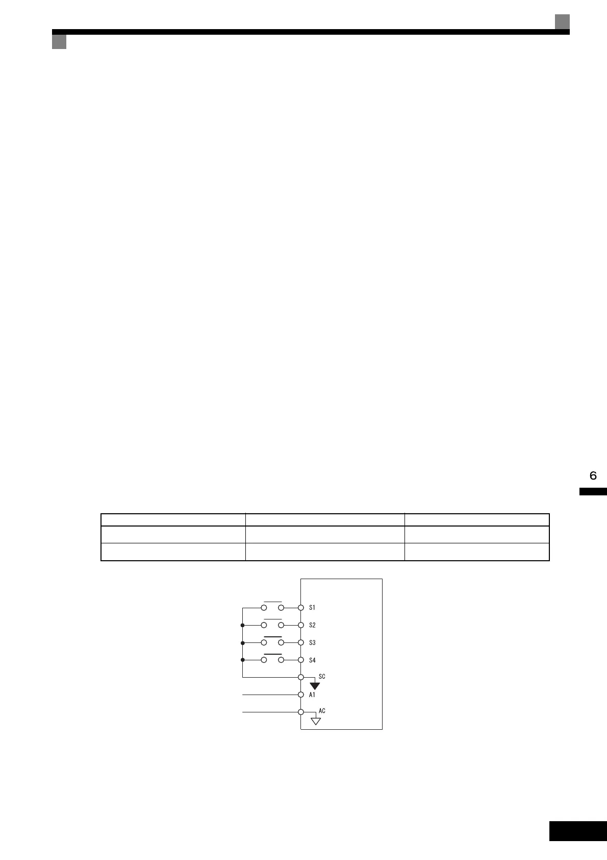
Connection Example and Time Chart
The time chart and settings example when the UP command is allocated to the multi-function contact input
terminal S3, and the DOWN command is allocated to terminal S4, are shown below.
Fig 6.53 Connection Example when UP/DOWN Commands Are Allocated
Constant Name Set Value
H1-01 Multi-function input (terminal S3) 10
H1-02 Multi-function input (terminal S4) 11
Inverter
0 to 10 V analog
signal
Forward
operation/Stop
Reverse
operation/Stop
Up command
Down command
Sequence
common
Frequency
reference lower limit
TOE-S616-60.1.book 81 ページ 2017年8月4日 金曜日 午後3時41分

 Loading...


