6
-90
Selecting Analog Monitor Items
The digital operator monitor items (U1- [status monitor]) are output from multi-function analog output
terminals FM-AC and AM-AC. Refer to Chapter 5 User Constants, and set the values for the part of U1-
(status monitor).
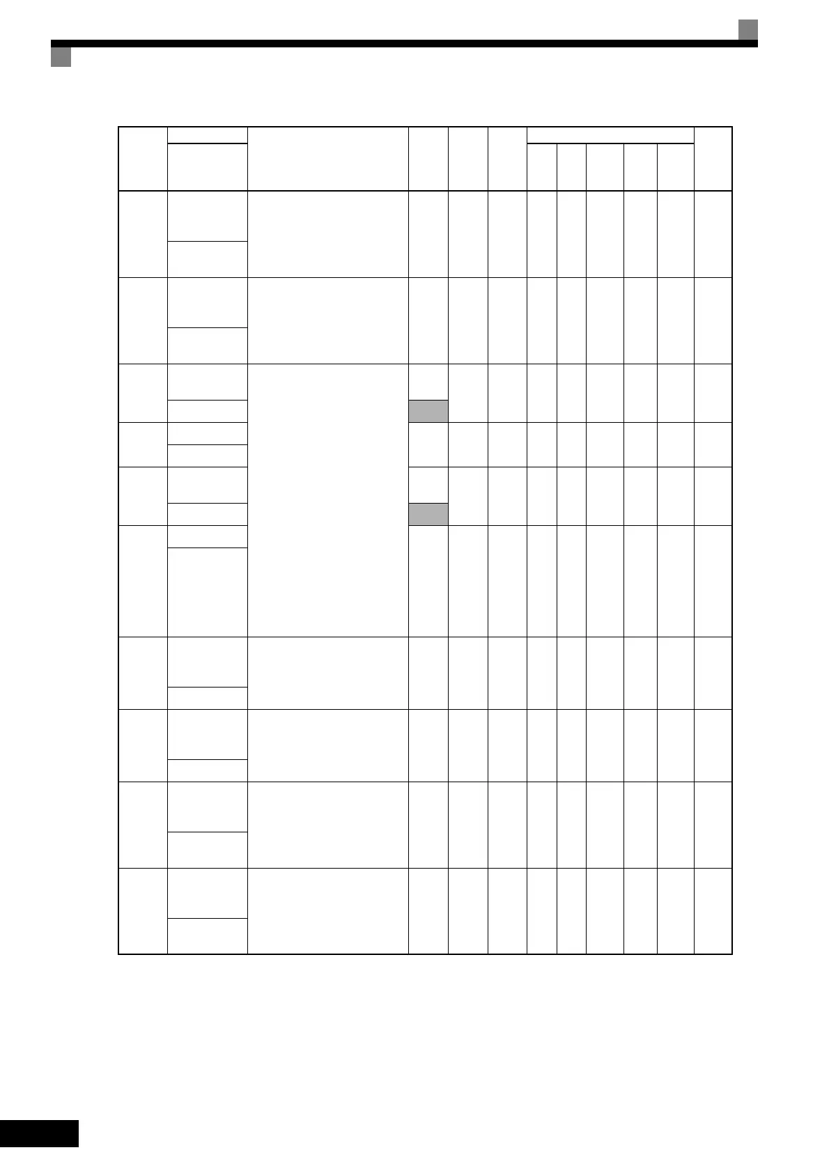
H4-07
Analog output 1
signal level
selection
Sets the signal output level for
multi-function output 1 (terminal
FM)
0: 0 to +10 V output
1: -10 to 10 V output
0 or 1 0 No A A A A A 423H
AO Level
Select1
H4-08
Analog output 2
signal level
selection
Sets the signal output level for
multi-function output 2 (terminal
AM).
0: 0 to +10 V output
1: -10 to 10 V output
0 or 1 0 No A A A A A 424H
AO Level
Select2
F4-01
Channel 1 mon-
itor selection
Effective when the Analog Moni-
tor Board is used.
Monitor selection:
Set the number of the monitor
item to be output. (U1-)
Gain:
Set the multiple of 10 V for out-
putting monitor items.
4, 10 to 14, 25, 28, 34, 39, 40 can-
not be set. 29 to 31 and 41 are not
used. When the AO-12 Analog
Monitor Board is used, outputs of
± 10 V are possible. To output ±
10 V, set F4-07 or F4-08 to 1.
When the AO-08 Analog Monitor
Board is used, only outputs of 0 to
+10 V are possible.
A meter calibration function is
available.
1 to 45
2 No A A A A A 391H
AO Ch1 Select
1 to 99
F4-02
Channel 1 gain
0.00 to
2.50
1.00 Yes A A A A A 392H
AO Ch1 Gain
F4-03
Channel 2 mon-
itor selection
1 to 45
3 No A A A A A 393H
AO Ch2 Select
1 to 99
F4-04
Channel 2 gain
0.00 to
2.50
0.50 Yes A A A A A 394H
AO Ch2 Gain
F4-05
Channel 1 out-
put monitor
bias
Sets the channel 1 item bias to
100%/10 V when the Analog
Monitor Board is used.
-10.0
to 10.0
0.0 Yes A A A A A 395H
AO Ch1 Bias
F4-06
Channel 2 out-
put monitor
bias
Sets the channel 2 item bias to
100%/10 V when the Analog
Monitor Board is used.
-10.0
to 10.0
0.0 Yes A A A A A 396H
AO Ch2 Bias
F4-07
Analog output
signal level for
channel 1
0: 0 to 10 V
1: -10 to +10 V
0 or 1 0 No A A A A A 397H
AO Opt Level
Sel
F4-08
Analog output
signal level for
channel 2
0: 0 to 10 V
1: -10 to +10 V
0 or 1 0 No A A A A A 398H
AO Opt Level
Sel
Con-
stant
Number
Name
Description
Setting
Range
Factory
Setting
Change
during
Opera-
tion
Control Methods
MEMO
BUS
Regis-
ter
Display
V/f
V/f
with
PG
Open
Loop
Vector
1
Flux
Vec-
tor
Open
Loop
Vector
2
TOE-S616-60.1.book 90 ページ 2017年8月4日 金曜日 午後3時41分

 Loading...


