6
-120
* 1. The factory setting depends on the Inverter capacity. The value for a 200 V Class Inverter of 0.4 kW is given.
* 2. The setting range is from 10% to 200% of the Inverter rated output current. The value for a 200 V Class Inverter for 0.4 kW is given.
For the motor no-load current, set E2-03 to a value less than that of E2-01.
* 3. The setting range depends on the Inverter capacity. The value for a 200 V Class Inverter of 0.4 kW is given. The upper limit depends on the setting of
E2-01.
Manual Motor Constant Setting Methods
The motor constants settings methods are given below. Make (enter) settings referring to the motor test report.
Motor Rated Voltage Setting
Set E2-01 to the rated current on the motor nameplate.
Motor Rated Slip Setting
Set E2-02 to the motor rated slip calculated from the number of rated rotations on the motor nameplate.
Amount of motor rated slip = Motor rated frequency (Hz) - No. of rated rotations (min
−1
) × No. of motor
poles/120.
Motor No-Load Current Setting
Set E2-03 to the motor no-load current using the rated voltage and rated frequency. The motor no-load current
is not normally written on the motor nameplate. Consult the motor manufacturer.
Factory setting is the no-load current value for a standard Yaskawa 4-pole motor.
Number of Motor Poles Setting
Set the number of motor poles (number of poles) as written on the motor nameplate. E2-04 is not displayed
when V/f control or open-loop vector control is selected.
Motor Line-to-Line Resistance Setting
E2-05 is set automatically when performing motor line-to-line resistance autotuning. When you cannot per-
form tuning, consult the motor manufacturer for the line-to-line resistance value. Calculate the resistance from
the line-to-line resistance value in the motor test report using the following formula, and then make the setting
accordingly.
• E-type isolation: [Line-to-line resistance (Ω) at 75°C of test report] × 0.92 (Ω)
• B-type isolation: [Line-to-line resistance (Ω) at 75°C of test report] × 0.92 (Ω)
• F-type isolation: [Line-to-line resistance (Ω) at 115°C of test report] × 0.87 (Ω)
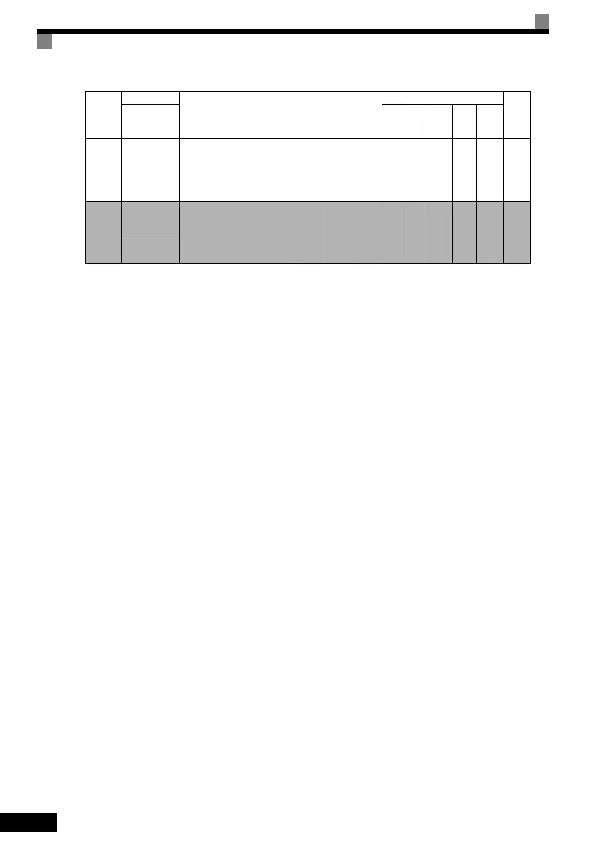
E2-10
Motor iron loss
for torque com-
pensation
Sets motor iron loss in W units.
0 to
65535
14 W
*1
No A A No No No 317H
Tcomp Iron
Loss
E2-12
Motor iron sat-
uration coeffi-
cient 3
Sets the motor iron saturation
coefficient at 130% of magnetic
flux.
This constant is automatically set
during rotational autotuning.
1.30 to
1.60
1.30 No No No A A A 328H
Saturation
Comp3
Con-
stant
Number
Name
Description
Setting
Range
Factory
Setting
Change
during
Opera-
tion
Control Methods
MEMO
BUS
Regis-
ter
Display
V/f
V/f
with
PG
Open
Loop
Vector
1
Flux
Vec-
tor
Open
Loop
Vector
2
TOE-S616-60.1.book 120 ページ 2017年8月4日 金曜日 午後3時41分

 Loading...


