Connection Diagram
2-
9
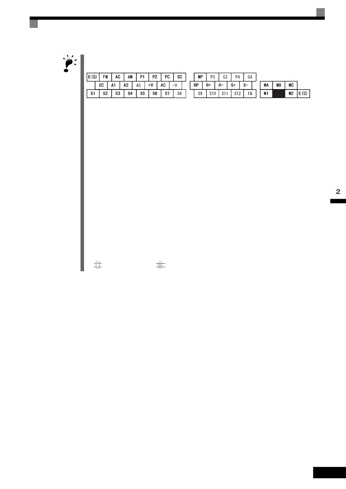
1. Control circuit terminals are arranged as shown below.
2. The output current capacity of the +V and −V terminals are 20 mA. Do not short-circuit between the +V, −V,
and AC terminals. Doing so may result in a malfunction or a breakdown of the Inverter.
3. Disable the stall prevention during deceleration (set constant L3-04 to 0) when using a Braking Resistor
Unit. If this user constant is not changed to disable stall prevention, the system may not stop during decel-
eration.
4. Main circuit terminals are indicated with double circles and control circuit terminals are indicated with single
circles.
5. The wiring for a motor with a cooling fan is not required for self-cooling motors.
6. PG circuit wiring (i.e., wiring to the PG-B2 Board) is not required for control without a PG.
7. Sequence input signals S1 to S12 are labeled for sequence connections (0 V common and sinking mode)
for no-voltage contacts or NPN transistors. These are the default settings.
For PNP transistor sequence connections (+24V common and sourcing mode) or to provide a 24-V exter-
nal power supply, refer to Table 2.13.
8. The multi-function analog output is a dedicated meter output for an analog frequency meter, ammeter, volt-
meter, wattmeter, etc. Do not use this output for feedback control or for any other control purpose.
9. DC reactors to improve the input power factor are built into 200 V Class Inverters for 18.5 to 110 kW and
400 V Class Inverters for 18.5 to 300 kW. A DC reactor is thus an option only for Inverters for 15 kW or
less.
10.Set constant L8-01 to 1 when using a breaking resistor (model ERF). When using a Braking Resistor Unit,
a shutoff sequence for the power supply must be made using a thermal relay trip.
11.The minimum permissible load of a multi-function contact output and an error contact output is 10 mA. Use
a multi-function open-collector output for a load less than 10 mA.
12.Do not ground nor connect the AC terminal on the control circuit to the unit. Doing so may result in a mal-
function or a breakdown of the Inverter.
13.If turning off the power only for the main circuit but leaving the power ON for the control circuit, use a sep-
arate power supply for the control circuit and a specially designed Inverter, which are sold as options.
14. indicates shield wire and indicates shielded twisted-pair wire.
TOE-S616-60.1.book 9 ページ 2017年8月4日 金曜日 午後3時41分

 Loading...


