8
-6
Procedure for Changing Constants through Communications
For 400-V class Inverters of 55 kW to 300 kW with SPEC: E and later, take safety measures such as the instal-
lation of an emergency-stop switch before adjusting constants. Failure to do so may result in injury caused by
the motor accidentally rotating during stationary autotuning performed by the Inverter when the constants are
adjusted.
After replacing the control board, write in all of the constants to the new board with MEMOBUS communica-
tions or a Communications Option Board.
Next, be sure to perform autotuning to make adjustments after shipping.
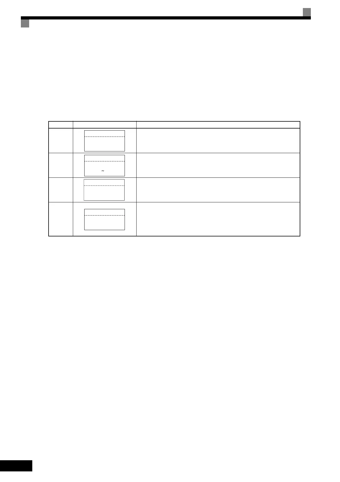
Step No. Digital Operator Display Description
1
Set T1-01 (Autotuning mode selection) to 3 (Shipping adjustment).
2
Press the Increment Key to view the motor rated power display. Set T1-02
(Motor output power) to the capacity of the connected motor.
3
Press the Increment Key to view the motor rated current display. Set T1-04
(Motor rated current) to the value of motor rated current.
4
Press the Increment Key to view the shipping adjustment display.
After confirming that the motor has been connected, press the RUN Key to
start autotuning.
Note: Do not touch the motor terminals. Although the motor does not rotate,
voltage is being supplied to the motor though the motor is not rotating.
-A.TUNE-
Tuning Mode Sel
T1-01=3
Shipping Ajust
"2"
-DRIVE-
Mtr Rated Power
T1-02=55.00kW
(3.00 650.00)
"55.00kW"
-DRIVE-
Rated Current
T1-04=95.0A
(16.5㨪330.0)
"95.0A"
-DRIVE-
Shipping Adjust
0Hz/ 0.0A
Tuning Ready ?
Press RUN Key
TOE-S616-60.1.book 6 ページ 2017年8月4日 金曜日 午後3時41分

 Loading...


