10
-14
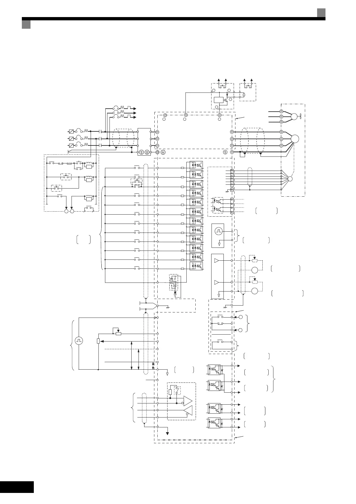
Wiring Example
This example shows wiring for conforming to undervoltage reference.
* 1. The main circuit is separated from the terminal cover for safety reasons.
* 2. The contact output circuit is separated from the main circuit and the control circuit by reinforced insulation.
It can be connected to extra-low voltage circuits or circuits that are 250 VAC 1 A, 30 VDC 1 A or less.
* 3. The control circuit is an extra-low voltage circuit and separated from the main circuit and the contact output circuit by reinforced insulation. Always
connect it to extra-low voltage circuits.
Fig 10.6
P2
PC
P1
MA
MB
MC
M1
M2
AC
MP
T/L3
S/L2
R/L1
1MCCB
Fuse
T
S
R
S5
S8
S1
S2
S3
S4
IG
R-
R+
S-
S+
+ 1 + 3
FM
AM
AC
E(G)
AM
FM
+
+-
-
20k
Ω
20k
Ω
SC
+24V
S6
S7
P
P
4 to 20mA
0 to +10V
RP
+V
A1
A2
AC
0V
2kΩ
2kΩ
2
1
3
E (G)
A3
0 to +10V
P
-V
( -15V 20mA)
PG
1
2
3
4
5
6
PG-B2
TA1
TA3
TA2
1
2
3
4
H
B
G
A
F
C
D
U
U/T1
V/T2
W/T3
IM
V
W
IM
FU
FV
FW
FU
FV
FW
2MCCB
MC
SA
2MCCB THRX OFF
ON
MC
MC
SA
THRX
21
21
SA
TRX
MC
TRX
MA
MC
MA
MC
43
-
-
-
+
0
0
B
P
43 21
+
*
1
*
2
*
3
Vm
3-phase power
200 to 240 V
50/60 Hz
Noise
filter
Braking Unit
(optional)
Thermal relay
trip contact
Level
detector
Braking Resistor Unit
(optional)
Thermal switch
contact
Inverter
CIMR-G7A2018
Cooling fan
Motor
Fault contact
for motor cooling fan
Thermal relay trip contact
for Braking Resistor Unit
Thermal relay trip contact
contact inputs
Multi-function
Factory
settings
(Main speed switching)
External
baseblock command
S9
Multi-step speed
reference 3
S10
Multi-step speed
reference 4
S11
Acc/dec time 1
+24V 8mA
S12
Emergency stop
(NO)
Forward Run/Stop
Reverse Run/Stop
External fault
Fault reset
Multi-step speed reference 1
Multi-step speed
reference 2
Jog frequency
selection
Thermal switch contact
for Braking Unit
CN5 (NPN setting)
(optional)
MEMOBUS
communications
RS-485/422
Pulse train input
Frequency
Frequency setting
adjustment
setter
External
frequency
references
Terminating
resistance
Shield wire
connection
terminal
Master speed
pulse train
Frequency setting power
Master speed reference
Multi-function anlog input
Master speed reference
4 to 20 mA (250
Ω)
[0 to 10 V (20 k
Ω
) input]
+15 V, 20 mA
0 to 10 V (20 kΩ)
0 to 10 V (20 kΩ)
Factory setting:
Not used
0 to 32 kHz (3 kΩ)
High level: 3.5 to 13.2 V input
Open collector 1
Open collector 2
Multi-function
open-collector outputs
48 VDC 50 mA max.
Default: Frequency
agree signal
Default: Zero-
speed
P3
C3
Open collector 3
Factory setting:
Inverter operation
ready
P4
C4
Open collector 4
Factory setting:
minor fault
Error contact output
250 VAC, 10 mA min. 1 A max.
30 VDC, 10 mA min. 1 A max.
Multi-function contact output
250 VAC, 10 mA min. 1 A max.
30 VDC, 10 mA min. 1 A max.
Default: Running
signal
Multi-function analog output 1
-10 to 10 V 2 mA
Default: Output frequency
0 to +10 V
Default: Output current
0 to +10 V
-10 to 10 V 2 mA
Multi-function analog output 2
Ammeter adjustment
Ammeter adjustment
Pulse train output
Default: Output
frequency
0 to 32 kHz (2.2 kΩ)
Pulse monitor output
30 mA max.
Wiring distance:d
30 m max.
Shielded twisted-pair
wires
Pulse A
Pulse B
TOE-S616-60.1.book 14 ページ 2017年8月4日 金曜日 午後3時41分

 Loading...


