Conformance to CE Markings
10-
17
EMC Directive
Varispeed G7-Series Inverters satisfy testing for conformance to the EMC Directive under the conditions
described in European Standard EN61800-3:2004+A1:2012.
Installation Method
In order to ensure that the machinery or installation incorporating the Inverter conforms to the EMC Directive,
perform installation according to the method below.
• Install a noise filter that conforms to European Standards on the input side. (Refer to Table 10.5 EMC
Noise Filters).
• Use a shielded line or metal piping for wiring between the Inverter and Motor. Make the wiring as short as
possible.
• To suppress harmonics, install a DC reactor in CIMR-G7A20P4, 20P7, 40P4, and 40P7 models. (Refer to
Table 10.6 DC Reactors for Suppressing Harmonics.)
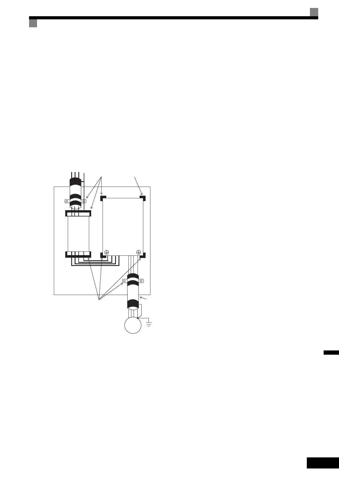
Fig 10.7 Installation Method for Filter and Inverter (CIMR-G7A20P4 to 2015, 40P4 to 4015)
R/L1, S/L2, T/L3 PE
IM
Remove the paint on the ground side.
Inverter
Inputs
Filter
Outputs
Wiring length: 10 m max. (category C1, CIMR-G7A20P4 to CIMR-G7A2011 or
CIMR-G7A40P4 to CIMR-G7A4015)
50 m max. (category C2, CIMR-G7A20P4 to CIMR-G7A2015 or
CIMR-G7A40P4 to CIMR-G7A4015)
Remove the paint on the ground side.
Wiring length:
40 cm max.
Metallic plate
R/L1, S/L2, T/L3
U/T1, V/T2, W/T3
TOE-S616-60.1.book 17 ページ 2017年8月4日 金曜日 午後3時41分

 Loading...


