EasyManuals Logo

YASKAWA Varispeed G7 Series User Manual

YASKAWA Varispeed G7 Series
541 pages
To Next Page IconTo Next Page
To Previous Page IconTo Previous Page
Page #532 background imageLoading...
Page #532 background image
10
-44
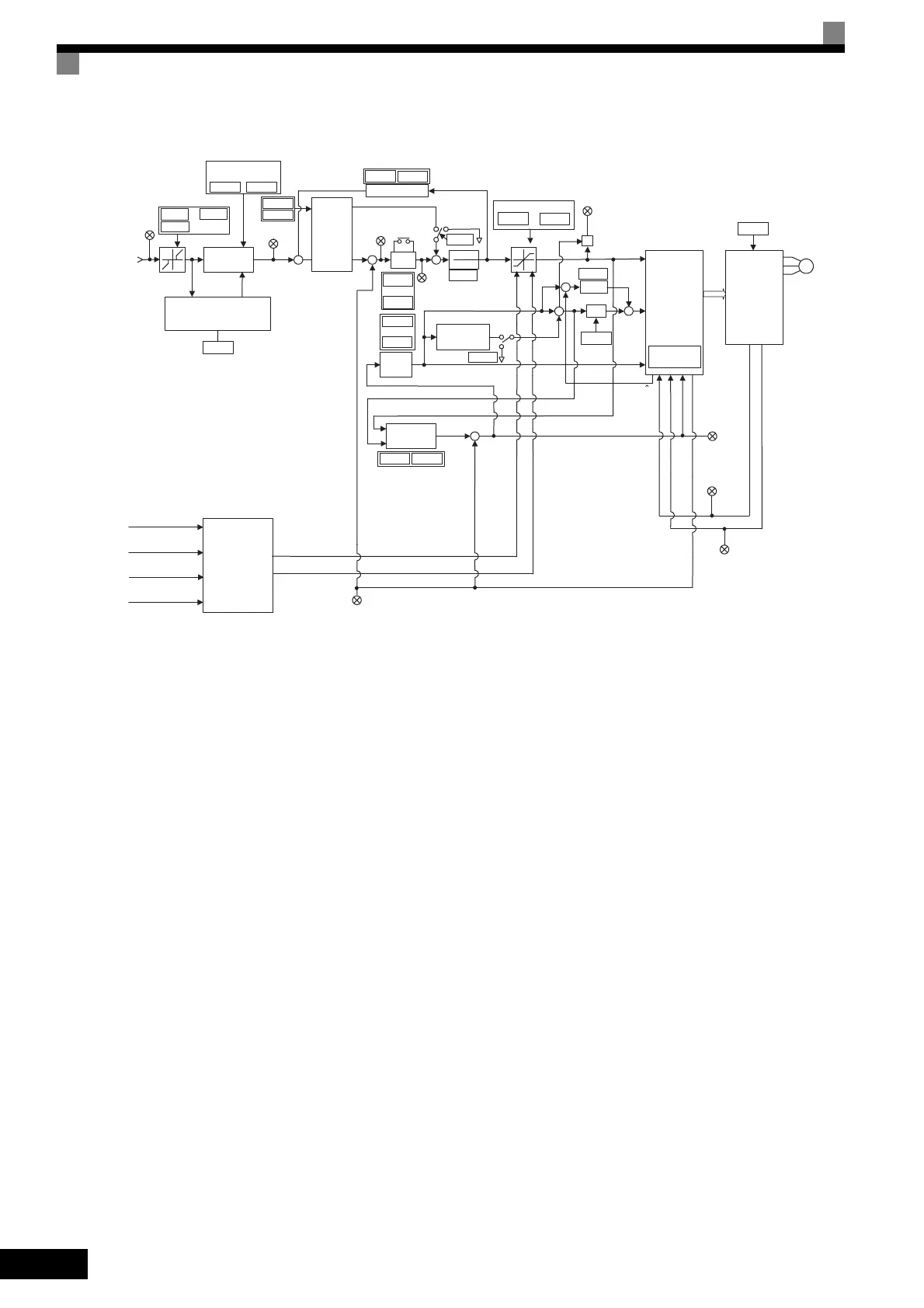
Control Block Diagram for Open-loop Vector 2 Control
Fig 10.26 Control Block Diagram for Open-loop Vector 2 Control (A1-02 = 4)
Soft starter
L3-04
U1-20
f0
+
U1-09
×
φ
*
iq
*
U1-02
iqfb
idfb
fout
+
U1-19
U1-18
e
*
C6-11
SFS output
Torque reference tro
Output
frequency
Motor secondary current
Motor
excitation
current
Drooping
IM
ASR
IRST
(Integral
short-circuit)
U1-21
ASR input
1
1+ST
d2-01
d2-03
E1-09
to
+
+
N5-01
C5-01
C5-04
C5-06
fnfb
+
+
fs
*
U1-22
ASR output
E1-04
E1-13
L7-01
L7-04
Torque limit
to
E2-03
IM
id
*
+
+
d6-03
C1-01
C1-02
tlim1
Torque limit 1
tlim2
Torque limit 2
tlim4
Torque limit 3
tlim5
Torque limit 4
Forward
Reverse
U1-05
Motor speed (estimated)
AφR
+
+
+
d6-05
φ
N5-02
N5-03
b7-01
b7-02
C3-01
E2-02
V/f
pattern
to
to
Torque limit
selection circuit
Stall prevention processing
(deceleration rate correction)
Inverter
Vector
calculator
Slip frequency
calculation
Field forcing
Feedforward
control
Speed
calculator
Acceleration and
deceleration times
Frequency
reference
U1-01
Speed
reference
fref
TOE-S616-60.1.book 44 ージ 017年8月4日 金曜日 午後3時41

Table of Contents

Questions and Answers:

Question and Answer IconNeed help?

Do you have a question about the YASKAWA Varispeed G7 Series and is the answer not in the manual?

YASKAWA Varispeed G7 Series Specifications

General IconGeneral
BrandYASKAWA
ModelVarispeed G7 Series
CategoryInverter
LanguageEnglish

Related product manuals