Installing and Wiring Option Boards
2-
41
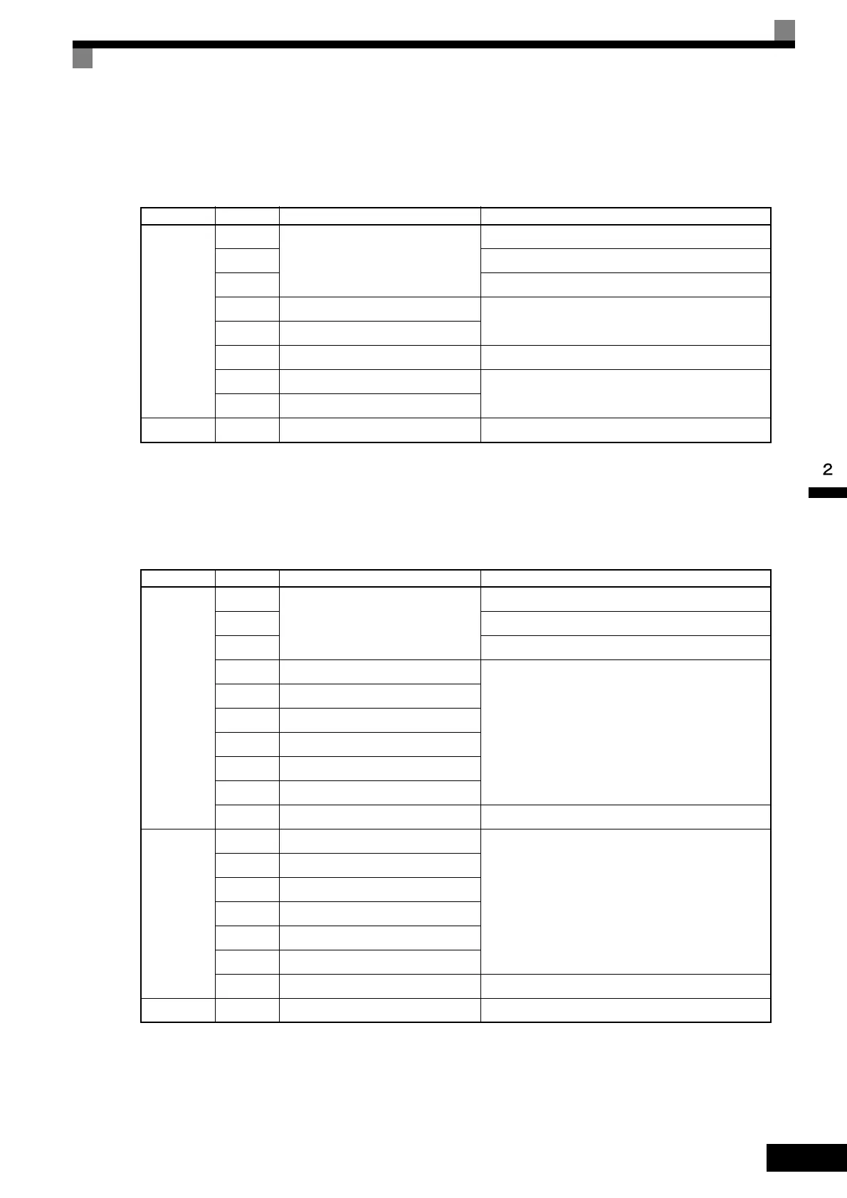
PG-D2
The terminal specifications for the PG-D2 are given in the following table.
* 5 VDC and 12 VDC cannot be used at the same time.
PG-X2
The terminal specifications for the PG-X2 are given in the following table.
* 5 VDC and 12 VDC cannot be used at the same time.
Table 2.17 PG-D2 Terminal Specifications
Terminal No. Contents Specifications
TA1
1
Power supply for pulse generator
12 VDC (±5%), 200 mA max.*
2 0 VDC (GND for power supply)
3 5 VDC (±5%), 200 mA max.*
4 Pulse input + terminal
Line driver input (RS-422 level input)
Maximum response frequency: 300 kHz
5 Pulse input - terminal
6 Common terminal –
7 Pulse monitor output + terminal
Line driver output (RS-422 level output)
8 Pulse monitor output - terminal
TA2 (E) Shield connection terminal –
Table 2.18 PG-X2 Terminal Specifications
Terminal No. Contents Specifications
TA1
1
Power supply for pulse generator
12 VDC (±5%), 200 mA max.*
2 0 VDC (GND for power supply)
3 5 VDC (±5%), 200 mA max.*
4 A-phase + input terminal
Line driver input (RS-422 level input)
Maximum response frequency: 300 kHz
5 A-phase - input terminal
6 B-phase + input terminal
7 B-phase - input terminal
8 Z-phase + input terminal
9 Z-phase - input terminal
10 Common terminal 0 VDC (GND for power supply)
TA2
1 A-phase + output terminal
Line driver output (RS-422 level output)
2 A-phase - output terminal
3 B-phase + output terminal
4 B-phase - output terminal
5 Z-phase + output terminal
6 Z-phase - output terminal
7 Control circuit common Control circuit GND
TA3 (E) Shield connection terminal –
TOE-S616-60.1.book 41 ページ 2017年8月4日 金曜日 午後3時41分

 Loading...


