3
-4
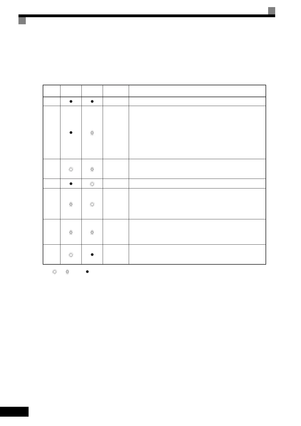
The following table shows the relationship between the indicators on the RUN and STOP Keys and the
Inverter conditions.
The indicators are lit, unlit or blinking reflecting the order of priority.
Note : Lit : Blinking : Not lit
* If planning to run the Inverter again, first turn OFF the Run Command and Emergency Stop Command from the control circuit terminal and send the Run
Command.
Table 3.2 Relation of Inverter to RUN and STOP Indicators
Priority
RUN
Indicator
STOP
Indicator
Inverter
Status
Conditions
1 Stopped Power supply is shut down.
2 Stopped*
Emergency stop
• Stop Command is sent from the Digital Operator when the control cir-
cuit terminals were used to operate the Inverter.
• Emergency Stop Command is sent from the control circuit terminal.
Switched from LOCAL (operation using the Digital Operator) to
REMOTE (operation using the control circuit terminals) when the Run
Command is sent from the external terminal.
Switched from the Quick or Advanced Quick programming mode to the
Drive mode when the Run Command is sent from the external terminal.
3 Stopped
The Inverter is run at a frequency below the minimum output frequency.
The Run Command is carried out when the External Baseblock Com-
mand using the multi-function contact input terminal is issued.
4 Stopped Stopped
5 Running
During deceleration to a stop
During DC injection braking when using the multi-function contact input
terminal.
During initial excitation of DC injection braking while the Inverter is
stopped.
6 Running
During emergency deceleration
• Stop Command is sent from the Digital Operator when operating the
Inverter using the control circuit terminals.
• Emergency Stop Command is sent from the control circuit terminal.
7 Running
Run Command is issued.
During initial excitation of DC injection braking when starting the
Inverter.
TOE-S616-60.1.book 4 ページ 2017年8月4日 金曜日 午後3時41分

 Loading...


