7. Programming Features
153
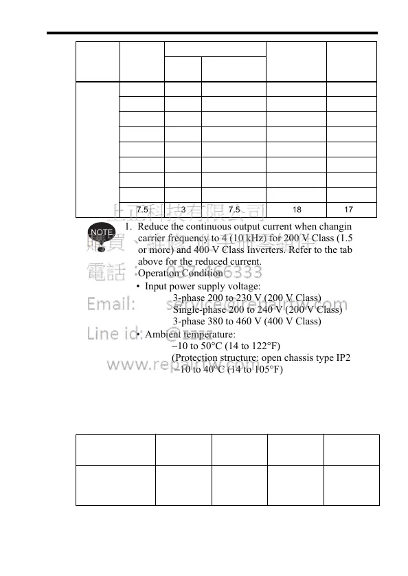
1. Reduce the continuous output current when changing the
carrier frequency to 4 (10 kHz) for 200 V Class (1.5 kW
or more) and 400 V Class Inverters. Refer to the table
above for the reduced current.
Operation Condition
• Input power supply voltage:
3-phase 200 to 230 V (200 V Class)
Single-phase 200 to 240 V (200 V Class)
3-phase 380 to 460 V (400 V Class)
• Ambient temperature:
−10 to 50°C (14 to 122°F)
(Protection structure: open chassis type IP20)
−10 to 40°C (14 to 105°F)
(Protection structure: top closed type IP20,
enclosed wall-mounted type NEMA 1 (TYPE 1))
2. If the wiring distance is long, reduce the Inverter carrier
frequency as described below.
3. Set the Carrier Frequency Selection (n080) to 1, 2, 3, or 4
when using vector control mode. Do not set it to 7, 8, or 9.
400 V
3-phase
0.37 3 7.5 1.2 1.0
0.55 3 7.5 1.8 1.6
1.1 3 7.5 3.4 3.0
1.5 3 7.5 4.8 4.0
2.2 3 7.5 5.5 4.8
3.0 3 7.5 7.2 6.3
3.7 3 7.5 8.6 8.1
5.5 3 7.5 14.8 14.8
7.5 3 7.5 18 17.0
Wiring Distance
between Inverter
and Motor
Up to 30 m Up to 50 m Up to 100 m More than
100 m
Carrier Frequency
(n080 setting)
14.5 kHz or
less
(n080=5, 6)
10 kHz or
less
(n080=1, 2,
3, 4, 7, 8, 9)
5 kHz or
less
(n080=1, 2,
7, 8, 9)
2.5 kHz or
less
(n080=1, 7,
8, 9)
Voltage
Class (V)
Capacity
(kW)
Factory Setting Maximum
Continuous
Output Cur-
rent (A)
Reduced
Current
(A)
Setting Carrier Fre-
quency (kHz)
NOTE