30
5. Voltage drop should be considered when determining the wire size.
Voltage drop can be calculated using the following equation:
Phase-to-phase voltage drop (V)
= × wire resistance (Ω/km) × wiring distance (m) × current
(A) × 10
-3
Select a wire size so that voltage drop will be less than 2% of the
normal rated voltage. Increase the wire size according to the length
of the cable if there is a possibility that the voltage may drop.
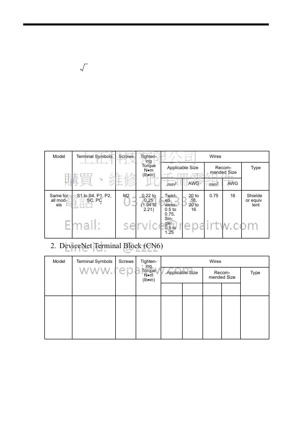
Wire and Terminal Screw Sizes
1. Control Circuits
2. DeviceNet Terminal Block (CN6)
Note: When removing the DeviceNet terminal block, hold the control circuit
terminal block (TB1).
Model Terminal Symbols Screws Tighten-
ing
Tor que
N•m
(lb•in)
Wires
Applicable Size Recom-
mended Size
Type
mm
2
AWG
mm
2
AWG
Same for
all mod-
els
S1 to S4, P1, P2,
SC, PC
M2 0.22 to
0.25
(1.94 to
2.21)
Twist-
ed
wires:
0.5 to
0.75,
Sin-
gle:
0.5 to
1.25
20 to
18,
20 to
16
0.75 18 Shielded
or equiva-
lent
Model Terminal Symbols Screws Tighten-
ing
Tor que
N•m
(lb•in)
Wires
Applicable Size Recom-
mended Size
Type
mm
2
AWG
mm
2
AWG
Same for
all mod-
els
V−, CAN_L,
shield, CAN_H,
V+
M3 0.5 to
0.6
Twist-
ed
wires:
0.2 to
2.5
24 to
12
Thin
DeviceNet
cable that
meets
DeviceNet
cable
specifica-
tions
3