10. Specifications
239
Recommended Peripheral Devices
It is recommended that the following peripheral devices be mounted
between the AC main circuit power supply and Varispeed V7 input ter-
minals R/L1, S/L2, and T/L3.
• MCCB (Molded-case Circuit Breaker)/Fuse:
Always connect for wiring protection.
• Magnetic Contactor:
Mount a surge suppressor on the coil. (Refer to the table shown
below.) When using a magnetic contactor to start and stop the
Inverter, do not exceed one start per hour.
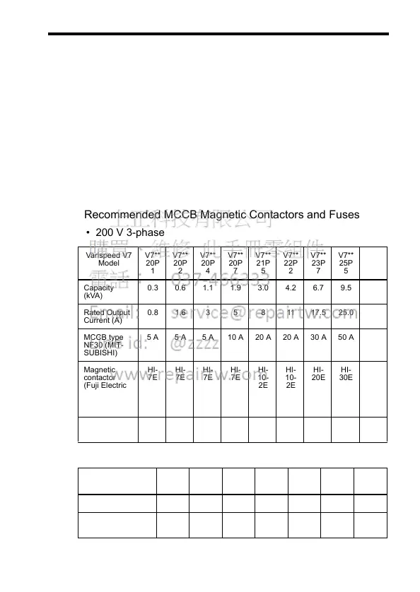
Recommended MCCB Magnetic Contactors and Fuses
• 200 V 3-phase
• 200 V Single-phase
Varispeed V7
Model
V7**
20P
1
V7**
20P
2
V7**
20P
4
V7**
20P
7
V7**
21P
5
V7**
22P
2
V7**
23P
7
V7**
25P
5
V7**
27P
5
Capacity
(kVA)
0.3 0.6 1.1 1.9 3.0 4.2 6.7 9.5 13.0
Rated Output
Current (A)
0.8 1.6 3 5 8 11 17.5 25.0 33.0
MCCB type
NF30 (MIT-
SUBISHI)
5 A 5 A 5 A 10 A 20 A 20 A 30 A 50 A 60 A
Magnetic
contactor
(Fuji Electric
FA Compo-
nents &
Systems)
HI-
7E
HI-
7E
HI-
7E
HI-
7E
HI-
10-
2E
HI-
10-
2E
HI-
20E
HI-
30E
HI-
50E
Fuse (UL
Class RK5)
5 A 5 A 5 A 10 A 20 A 20 A 30 A 50 A 60 A
Varispeed V7
Model
V7**
B0P1
V7**
B0P2
V7**
B0P4
V7**
B0P7
V7**
B1P5
V7**
B2P2
V7**
B3P7
Capacity (kVA) 0.3 0.6 1.1 1.9 3.0 4.2 6.7
Rated Output
Current (A)
0.8 1.5 3 5 8 11 17.5