10. Specifications
231
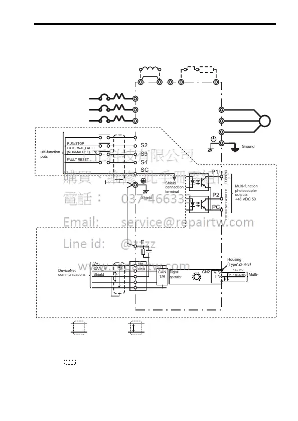
Standard Wiring
Example of a model with Digital Operator and analog volume
DC Reactor
(Optional)
Thermal Overload
Relay (Optional)
Braking Resistor
(Optional)
Shorting bar*1
MCCB
If a single-phase
power supply is being
used, use R and S.
FORWARD
RUN/STOP
REVERSE
RUN/STOP
FAULT RESET
Multi-function
inputs
Shield
connection
terminal
DeviceNet
communications
500 kbps max.
+24 VDC +/− 4%
FREQUENCY AGREED
RUNNING
Multi-function
photocoupler
outputs
+48 VDC 50 mA max.
Shielded twisted-pair cable
Shielded
: Only basic insulation (protective class 1, overvoltage category II) is provided for the
control circuit terminals. Additional insulation may be necessary in the end product to
conform to CE requirements.
+2 +1 -
B1 B2
R/L1
S/L2
T/L3
R
S
T
U/T1
V/T2
W/T3
SC
IM
P1
P2
PC
CAN
T/R
P
P
V+
CA
N_H
Shield
CAN
_L
V-
P
E
(
)
Red
White
Blue
Black
Shield
Ground
EXTERNAL FAULT
(NORMALLY OPEN)
S1
S2
S3
S4
*1 Shorting bar must be removed when connecting a DC reactor.
*2: A housing is required when using the CN2 terminal on the back side of the digital operator.
1m analog input cable (code no. WV201) is available for housing on request.
Multi-funciton
analog input
*
2
Housing
(
Type
:
ZHR-
3
)
Digital
operator
JVOP-140
MIN MAX
VIN
IIN
GND
CN2
0 to 10V
4 to 20mA
0V
P