9. Fault Diagnosis
211
Detected as
an alarm
only. Fault
contact out-
put is not ac-
tivated.
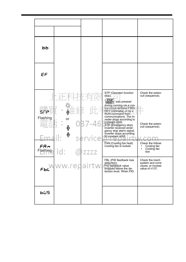
BB (External baseblock)
BASEBLOCK command
at multi-function termi-
nal is ON and the Invert-
er output is OFF (motor
coasting). Condition is
cleared when input com-
mand is removed.
Check the external cir-
cuit (sequence).
EF (Simultaneous FWD/
REV RUN commands)
When FWD and REV
RUN commands are si-
multaneously input for
over 500 ms, the Inverter
stops according to con-
stant n005.
Check the external cir-
cuit (sequence).
STP (Operator function
stop)
was pressed
during running via a con-
trol circuit terminal FWD/
REV command, or by a
RUN command from
communications. The In-
verter stops according to
constant n005.
STP (Emergency stop)
Inverter received emer-
gency stop alarm signal.
Inverter stops according
to constant n005.
Check the external cir-
cuit (sequence).
Check the external cir-
cuit (sequence).
FAN (Cooling fan fault)
Cooling fan is locked.
Check the following:
• Cooling fan
• Cooling fan connec-
tion
FBL (PID feedback loss
detection)
PID feedback value
dropped below the de-
tection level. When PID
feedback loss is detect-
ed, the Inverter operates
according to the n136
setting.
Check the mechanical
system and correct the
cause, or increase the
value of n137.
A communications fault
occurred.
Check communications
signals.
Alarm Display Inverter
Status
Description Causes and Correc-
tive Actions
Digital
Operator
RUN (Green)
ALARM (Red)
Flashing
or
Flashing
Flashing
Flashing
Flashing
Flashing