9. Fault Diagnosis
213
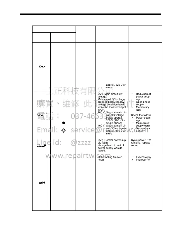
Fault Displays and Meanings
Fault Display Inverter
Status
Description Causes and Correc-
tive Actions
Digital
Operator
RUN (Green)
ALARM (Red)
Protective
Operation
Output is
turned OFF
and motor
coasts to a
stop.
OV (Main circuit
overvoltage)
Main circuit DC voltage
exceeded the
overvoltage detection
level because of exces-
sive regenerative ener-
gy from the motor.
Detection level:
200 V: Stop at main cir-
cuit DC voltage
below approx.
410 V
400 V: Stops at main cir-
cuit DC voltage of
approx. 820 V or
more
• Insufficient
Deceleration Time
(constants n020 and
n022)
• Lowering of negative
load (e.g., elevator)
⇓
• Increase
deceleration time.
• Connect optional
braking resistor.
UV1 (Main circuit low
voltage)
Main circuit DC voltage
dropped below the low-
voltage detection level
while the Inverter output
is ON.
200 V: Stops at main cir-
cuit DC voltage
below approx.
200 V (160 V for
single-phase)
400 V: Stops at main cir-
cuit DC voltage of
approx. 400 V or
more
• Reduction of input
power supply volt-
age
• Open phase of input
supply
• Momentary power
loss
⇓
Check the following:
• Power supply volt-
age
• Main circuit power
supply connections
• Terminal screws:
Loose?
UV2 (Control power sup-
ply fault)
Voltage fault of control
power supply was de-
tected.
Cycle power. If the fault
remains, replace the In-
verter.
OH (Cooling fin over-
heat)
Temperature increased
because of Inverter over-
load operation or intake
air temperature rise.
• Excessive load
• Improper V/f pattern
setting
• Insufficient
acceleration time if
the fault occurs dur-
ing acceleration
• Intake air tempera-
ture exceeding 50°C
(122°F)
• Cooling fan stops.
⇓
Check the following:
• Load size
• V/f pattern setting
(constants n011 to
n017)
• Intake air tempera-
ture.