10. Specifications
233
* DC power supply input terminal is not applied to CE/UL standard.
Control Circuit
Input
Sequence
S1 Multi-function input
selection 1
Factory setting closed:FWD run
open: REV run
Photo-
coupler
insulation,
24 VDC,
8mA
S2 Multi-function input
selection 2
Factory setting closed:REV run
open: FWD run
S3 Multi-function input
selection 3
Factory setting: External
fault (NO contact)
S4 Multi-function input
selection 4
Factory setting: Fault reset
SC Multi-function input
selection common
For control signal
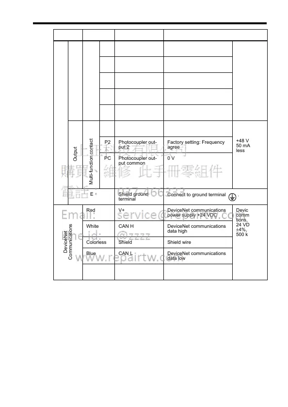
Output
Multi-function contact output
P1 Photocoupler out-
put 1
Factory setting: Run Photo-
coupler
output
+48 VDC,
50 mA or
less
P2 Photocoupler out-
put 2
Factory setting: Frequency
agree
PC Photocoupler out-
put common
0 V
E Shield ground
terminal
Connect to ground terminal .
DeviceNet
Communications
Red V+ DeviceNet communications
power supply +24 VDC
DeviceNet
communica-
tions,
24 VDC
±4%, up to
500 kbps
White CAN H DeviceNet communications
data high
Colorless Shield Shield wire
Blue CAN L DeviceNet communications
data low
Black V- DeviceNet communications
power supply GND
Type Terminal Name Function (Signal Level)