4. Wiring
37
• Braking Resistor Connection (Optional)
To connect the braking resistor, cut the protector on terminals
B1 and B2.
To protect the braking resistor from overheating, install a ther-
mal overload relay between the braking resistor and the
Inverter. This provides a sequence that turns OFF the power
supply with thermal relay trip contacts.
Failure to observe this warning may result in a fire.
Use this same procedure when connecting a Braking Resistor Unit.
Refer to page 232.
• Inverter Output
Connect the motor terminals to U/T1, V/T2, and W/T3.
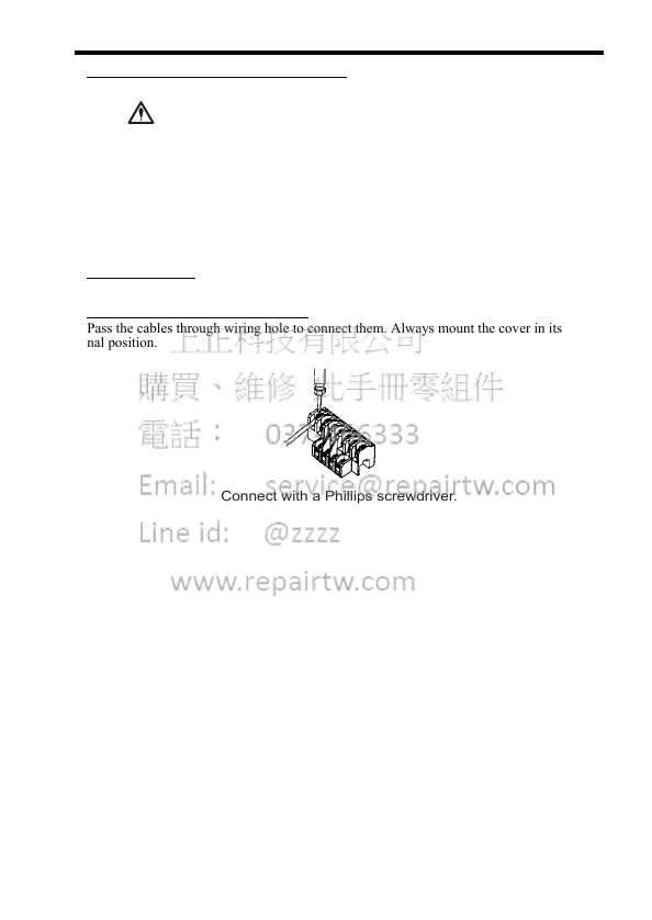
• Wiring the Main Circuit Terminals
Pass the cables through wiring hole to connect them. Always mount the cover in its origi-
nal position.
WARNING
Connect with a Phillips screwdriver.